
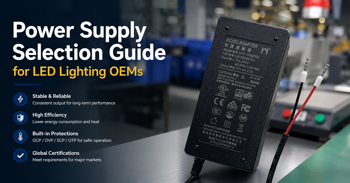
For LED lighting OEMs, the power supply—commonly referred to as the LED driver—directly determines the luminaire’s light output quality, lifespan, energy efficiency, and regulatory compliance. Unlike general-purpose power adapters that deliver a regulated DC voltage, LED drivers must manage output current with precision, accommodate dimming protocols, meet strict power factor and harmonic requirements, and survive the thermal and environmental conditions of the lighting installation.
This guide covers the power supply parameters that matter most to LED lighting system design: constant current versus constant voltage architectures, dimming compatibility, power quality considerations, thermal derating, IP rating selection, and certification pathways for global markets. The focus is on external and integrable AC/DC power supplies as used by LED lighting OEMs in commercial, industrial, and architectural applications.
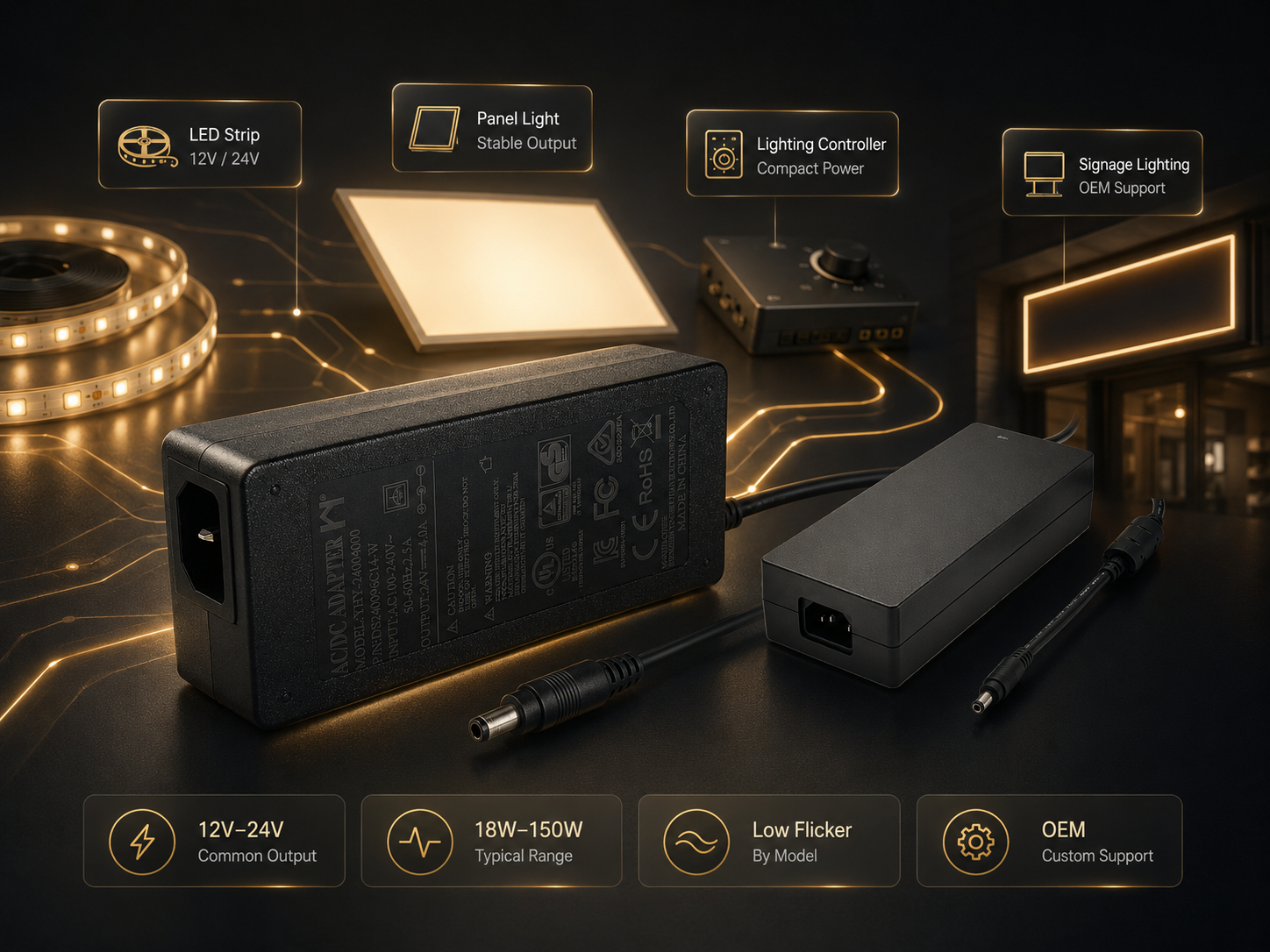
YHYadapter product positioning: YHYadapter provides regulated constant-voltage (CV) AC/DC power adapters suitable for use within LED lighting systems where a CV bus powers integrated current-limiting or driver stages. Dedicated constant-current (CC) LED drivers are discussed as industry architecture options and are not within YHYadapter’s current product scope.
Constant Current vs Constant Voltage — Which Architecture Suits Your Design?
The single most important decision in LED lighting power design is whether the application requires a constant current (CC) or constant voltage (CV) driver. These are fundamentally different output regulation modes, and selecting the wrong type can cause premature LED failure, inconsistent brightness, or system instability.
Constant Current (CC) Drivers regulate the output current to a fixed value while allowing the output voltage to vary within a specified range. These are the standard choice for direct LED array drive, where the forward voltage of the LED string shifts with temperature and binning variation. A CC driver delivers consistent current regardless of these shifts, maintaining uniform light output and protecting the LEDs from thermal runaway.
Typical CC driver output ratings: 350mA, 500mA, 700mA, 1050mA with voltage ranges such as 20–40VDC or 30–50VDC.
Constant Voltage (CV) Drivers regulate the output voltage to a fixed value (commonly 12V, 24V, or 48VDC) and supply current as demanded by the connected load. These are used for LED strip lighting, signage, and systems with integrated current-limiting resistors or individual CC regulator stages per channel.
The decision framework:
| Application Type | Recommended Architecture | Reason |
|---|---|---|
| Single LED array, downlight, track light | Constant Current | Direct drive, no additional current-limiting components |
| LED strip, signage, tape light | Constant Voltage | Multiple segments wired in parallel, each with local current limiting |
| Multi-channel color (RGB/CCT) | Constant Voltage | Each channel has its own CC regulator; shared CV bus is simpler |
| High-power COB LED module | Constant Current | COB modules require precisely regulated current for thermal safety |
| Dimmable architectural lighting | CC or CV (depends on dimming protocol) | 0–10V dimming works with both; DALI and Triac are driver-topology-dependent |
YHYadapter product scope: Constant-voltage (CV) AC/DC power adapters. For applications recommending constant-current architecture, OEMs source dedicated CC LED drivers from specialized lighting driver manufacturers. YHYadapter CV adapters may be used in systems where a regulated CV bus powers CC regulator stages or current-limited channels.
Why This Matters
- Using a CV driver for a direct LED array without current-limiting resistors results in uncontrolled current as LED forward voltage varies with temperature—this is the most common cause of premature LED failure in incorrectly designed systems.
- Using a CC driver for a system designed for CV (e.g., LED strips with built-in resistors) may cause the driver to operate outside its specified voltage range, triggering protection and reducing system reliability.
- Some advanced LED drivers support both CC and CV modes with a configurable output characteristic, but this flexibility comes at a cost premium.
What OEMs Should Do Now
- Determine whether your LED load requires strict current regulation (direct LED drive) or voltage regulation (parallel channels with local current limiting).
- For CC designs, specify the driver’s output voltage range to accommodate the LED array’s forward voltage tolerance, cold-start voltage rise, and end-of-life voltage shift.
- For CV designs, verify that the total load current at full brightness does not exceed the driver’s rated output current at the operating temperature.
Q: Can I use a standard CV power adapter to drive a single high-power LED module?
A: A standard CV adapter lacks current regulation. Without a current-limiting resistor or dedicated CC stage in series with the LED, the LED current will be uncontrolled. For direct LED drive, a CC driver or a CV adapter with an inline CC regulator is required.
Q: What happens if a CC driver’s output voltage range does not cover the LED array’s forward voltage?
A: If the LED array’s forward voltage falls below the driver’s minimum output voltage, the driver may operate in an unstable or high-ripple mode. If it exceeds the maximum, the driver will either shut down (overvoltage protection) or the LEDs will not reach full brightness. The driver’s voltage range must bracket the LED string voltage under all operating conditions.
Dimming Compatibility — What Every Lighting OEM Should Know

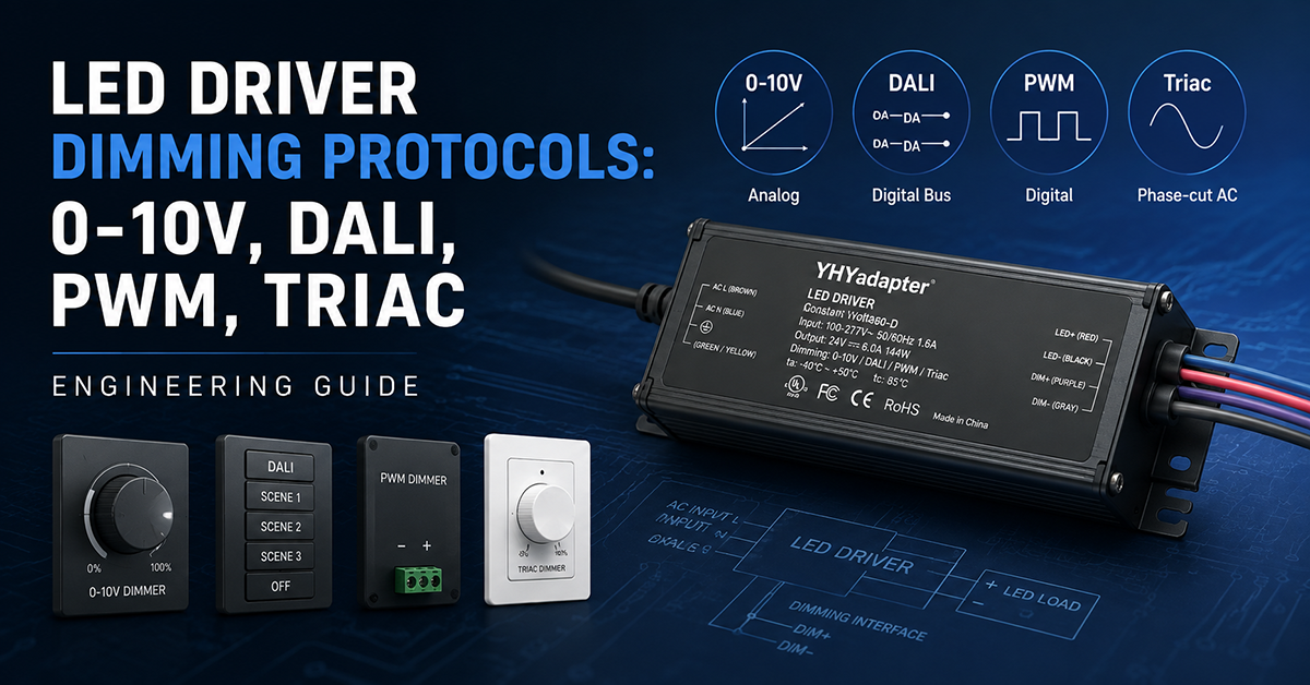
Dimming is no longer optional for commercial and architectural LED lighting. OEMs must ensure compatibility between the LED driver and the dimming control system. The four dominant dimming protocols each have distinct electrical interface requirements.
0–10V Dimming (IEC 60929 Annex E)
- Type: Analog, two-wire control (dimming positive and dimming common)
- Signal: 0–10VDC; 10V = 100% output, 0V = minimum (typically 1–10% depending on driver)
- Polarity-sensitive: reversing the dimming wires may prevent dimming or cause erratic behavior
- Compatibility: Works with CC and CV drivers. Most commercial-grade LED drivers support 0–10V as standard.
- Wiring: Low-voltage class 2 wiring from control system to driver; can share conduit with AC mains in some jurisdictions (verify local code)
DALI (Digital Addressable Lighting Interface, IEC 62386)
- Type: Digital, two-wire bus (DALI+ and DALI−)
- Signal: 16V DC bus with Manchester-coded digital commands; 1200 baud
- Addressable: Each DALI driver has a unique address (64 devices per DALI line)
- Compatibility: Designed specifically for LED drivers. Enables scene control, group addressing, and status feedback.
- Isolation: DALI bus is SELV; driver must provide galvanic isolation between DALI and AC mains
PWM Dimming (Pulse-Width Modulation)
- Type: Digital, high-frequency switching of the LED current
- Signal: Variable duty cycle at a fixed frequency (typically 200Hz–20kHz depending on driver design and application)
- Key concern: Visible flicker. PWM frequencies below 1kHz may be perceptible; frequencies above 20kHz eliminate visible flicker but increase switching losses
- Compatibility: Requires a driver with PWM input. CV systems use external PWM controllers; CC drivers often include a PWM dimming input.
Triac (Phase-Cut) Dimming (Forward-phase / Leading-edge)
- Type: AC mains phase control (legacy incandescent dimmer compatibility)
- Signal: Leading-edge or trailing-edge phase cut on the AC input
- Compatibility: The most challenging dimming method for LED drivers. Requires a driver specifically designed for Triac dimming, with a compatible minimum load to prevent dimmer misfiring.
- Risks: Driver may buzz, flicker, or refuse to start if the dimmer and driver are not explicitly tested together.
Why This Matters
- A driver that supports 0–10V dimming but is paired with a PWM control system will not dim at all—the two protocols are electrically incompatible.
- Triac dimming compatibility is system-specific, not driver-generic. Even a Triac-rated driver may behave differently with different dimmer brands.
- DALI drivers cost more per unit but enable programmable control, commissioning, and building-management integration that 0–10V cannot match.
What OEMs Should Do Now
- Identify the dimming protocol used in your target market’s standard installations: 0–10V is dominant in North American commercial lighting; DALI is common in European specification-grade projects; Triac is legacy retrofit.
- If offering multiple dimming options, design the luminaire to accept a family of driver models with identical mechanical footprint and electrical interface but different dimming input stages.
- For Triac-compatible products, test each driver-dimmer combination during product development—compatibility is not predictable from driver specifications alone.
Q: Can a single LED driver support both 0–10V and DALI dimming?
A: Some multi-protocol drivers accept both, but they typically require different control wiring or an auto-detect configuration. Most drivers are designed for one dimming protocol. Verify the driver’s datasheet for supported control inputs rather than assuming multi-protocol capability.
Q: What is the minimum dimming level for 0–10V LED drivers?
A: Most 0–10V LED drivers dim to 10% or 1% of full output. The minimum level is specified in the driver’s datasheet. Dimming below the specified minimum may cause the driver to shut off or operate with excessive current ripple.
Power Factor, Harmonics, and Efficiency Requirements
LED lighting installations with significant total power are subject to power factor correction (PFC) and harmonic current limits. The requirements vary by market, total power, and application type.
Power Quality Considerations by Market
| Market | Requirement Type | Key Standard Details | Application Scope |
|---|---|---|---|
| EU | Harmonic current limits | EN 61000-3-2 Class C — specific per-harmonic limits for lighting equipment >25W input power | Lighting equipment connected to public low-voltage supply |
| USA (Energy Star) | Minimum PF specification | Residential: PF ≥ 0.7; Commercial: PF ≥ 0.9 | Energy Star qualified products only |
| USA (FCC) | EMC | FCC Part 15 Subpart B (conducted and radiated emissions) | All digital electronic products |
| China | PF + harmonics | GB/T 18595 (EMC lighting), GB 17625.1 (harmonics) | Lighting equipment per national scope |
| International (project specs) | Depending on project | Common specification: PF ≥ 0.9 above 25W | Typically specified for commercial and architectural projects |
Power factor and harmonic requirements vary by market, product type, and power level. Verify requirements against the applicable standard edition and product classification for each target market.
Harmonic Content
EN 61000-3-2 Class C imposes specific limits on individual harmonic currents for lighting equipment exceeding 25W input power. Active PFC is a common method for meeting these limits, but alternative design approaches exist depending on the required performance level and applicable standard edition. Single-stage PFC designs (critical-conduction-mode boost PFC combined with the DC-DC stage) are common in 30W–150W LED drivers. Two-stage designs (dedicated PFC boost + LLC/PSFB isolated stage) are typical above 150W.
Efficiency varies by topology, load, and design. Efficiency data is design- and platform-dependent for any LED driver. Verify with the appropriate manufacturer’s test data for the specific model and operating point.
Why This Matters
- A luminaire with PF below 0.9 may be rejected from commercial lighting projects where power quality specifications are enforced by electrical consultants and building codes.
- EN 61000-3-2 Class C harmonic limits apply to lighting equipment above 25W input power in EU markets. Active PFC is a common method for compliance, but alternative design approaches exist depending on the applicable standard edition and required performance level.
- Higher driver efficiency reduces heat generation inside the luminaire enclosure, directly improving LED lifetime and reducing thermal management cost.
What OEMs Should Do Now
- Determine the target markets for your luminaire and map the PF and harmonic requirements at the design specification stage.
- For EU-bound products above 25W, verify that the driver meets EN 61000-3-2 Class C harmonic limits. Confirm with the driver supplier’s test report for the specific model and applicable standard edition.
- Consider the thermal impact of driver efficiency: a 150W driver at 90% efficiency dissipates 15W of heat inside the luminaire. Every percentage point of efficiency improvement reduces internal heat by approximately 1.5W at this power level.
Q: Do I need active PFC in a 20W LED driver for EU markets?
A: EN 61000-3-2 Class C harmonic limits apply to lighting equipment with input power above 25W. Below 25W, the requirements are typically relaxed, though designers may evaluate power quality approaches appropriate to the project specification.
Q: Can a high-PF LED driver cause compatibility issues with emergency lighting inverters?
A: Some emergency lighting inverters (central battery systems) have difficulty with LED drivers that include active PFC, because the PFC stage presents a non-linear load with high inrush current. Verify driver-inverter compatibility with both manufacturers’ test data before specifying.
Thermal Derating, IP Rating, and Environmental Design
LED lighting installations cover a wide range of environments—from controlled indoor commercial spaces to outdoor parking lots, damp locations, and high-temperature industrial settings. The driver’s thermal and ingress protection ratings must match the installation environment.
Thermal Derating
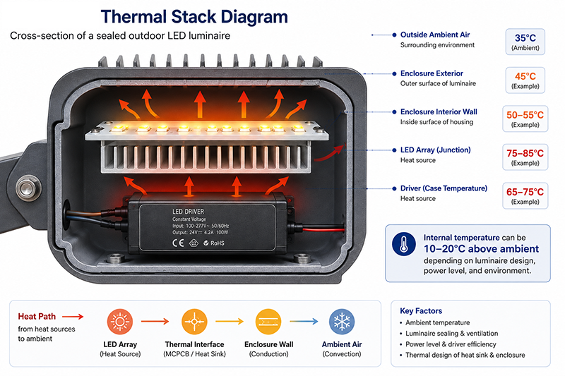
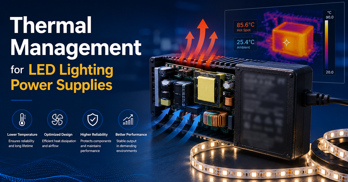
All LED drivers derate output power as ambient temperature increases. A typical 100W driver rated for operation up to 50°C may deliver full output only up to 40°C and linearly derate to 70% at 50°C.
Key thermal considerations:
- Case temperature (Tc) point: The driver’s datasheet specifies a maximum case temperature at which the driver can operate. This is measured at a defined location on the driver enclosure. Exceeding Tc triggers OTP or reduces lifespan.
- Lumen maintenance correlation: Higher driver operating temperature reduces the lifetime of electrolytic capacitors inside the driver, which is often the dominant wear-out mechanism for the entire luminaire.
- Enclosure ventilation: When the driver is installed inside a sealed luminaire, the ambient temperature inside the enclosure can be 10–20°C above the room ambient, substantially reducing the driver’s effective output capacity.
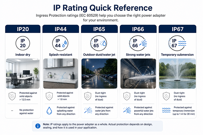
Ingress Protection (IP) Ratings
| IP Rating | Suitable Applications | Typical Locations |
|---|---|---|
| IP20 | Indoor dry locations | Offices, retail, warehouses (dry) |
| IP44 | Splash-resistant indoor | Bathrooms, kitchens, covered walkways |
| IP65 | Outdoor, dust-tight, water-jet resistant | Parking lots, façades, landscape lighting |
| IP66 | Outdoor, strong water jets | Tunnel lighting, car washes, marine |
| IP67 | Temporary submersion | Fountain lighting, flood lighting in flood-prone areas |
For outdoor LED lighting, the driver’s IP rating should be selected to match the installation environment’s requirements. A common pitfall is using an IP65 driver but failing to seal the AC input cable entry, which bypasses the driver’s IP protection at the connection point. Requirements depend on the specific installation location and applicable codes.
Operating Temperature Range
- Standard indoor: –20°C to +50°C (common for commercial LED drivers)
- Outdoor cold-start: –40°C (required for cold-climate installations; some drivers may not start reliably below –20°C without preheating)
- High-temperature industrial: Up to +70°C (derated output)
Operating-temperature range is model-specific and should be verified from the applicable datasheet.
Why This Matters
- A driver rated for 50°C ambient but installed inside a sealed outdoor luminaire exposed to direct sunlight may experience internal temperatures exceeding 70°C, causing the driver to shut down or fail within months.
- Outdoor LED lighting with inadequate IP rating can fail within a single rainy season due to water ingress and corrosion. IP65 or higher is commonly specified for outdoor luminaires, depending on the installation environment and applicable codes.
- Cold-start below −20°C can cause some drivers to fail to start due to electrolytic capacitor impedance increase or PFC controller startup issues. Verify cold-start capability from the driver datasheet for the expected installation climate.
What OEMs Should Do Now
- Measure or estimate the internal operating temperature of the luminaire enclosure during worst-case conditions (maximum ambient + solar gain + driver self-heating + LED self-heating). Select a driver rated for this temperature with adequate derating margin.
- For outdoor products, specify IP65 or IP66 drivers and ensure all cable entries (AC input, DC output, dimming) are properly sealed in the luminaire assembly.
- For cold-climate products, request cold-start test data from the driver supplier at the minimum expected ambient temperature.
Q: Can I place the LED driver outside the luminaire to reduce thermal stress?
A: Yes, remote driver placement is a common strategy for high-temperature or sealed luminaire designs. The driver is housed separately (typically in an IP65 junction box or raceway) where ambient temperature is lower. This improves driver lifetime but adds installation complexity and cost.
Q: What is the typical lifetime of an LED driver at its rated operating temperature?
A: Driver lifetime is primarily determined by electrolytic capacitor lifetime and is specified at a defined case temperature (Tc). A driver rated for 50,000 hours at Tc = 70°C will have a different lifetime at higher or lower case temperatures. Lifetime figures should be verified from the manufacturer’s datasheet and are model-dependent.
Certification Pathways for LED Lighting Power Supplies
LED lighting power supplies must carry the relevant safety, EMC, and energy-efficiency certifications for their target markets. The standards landscape differs from general power adapters because LED drivers are classified as lighting controlgear.
| Market | Safety / Compliance Path | Key Standards | Typical Timeline |
|---|---|---|---|
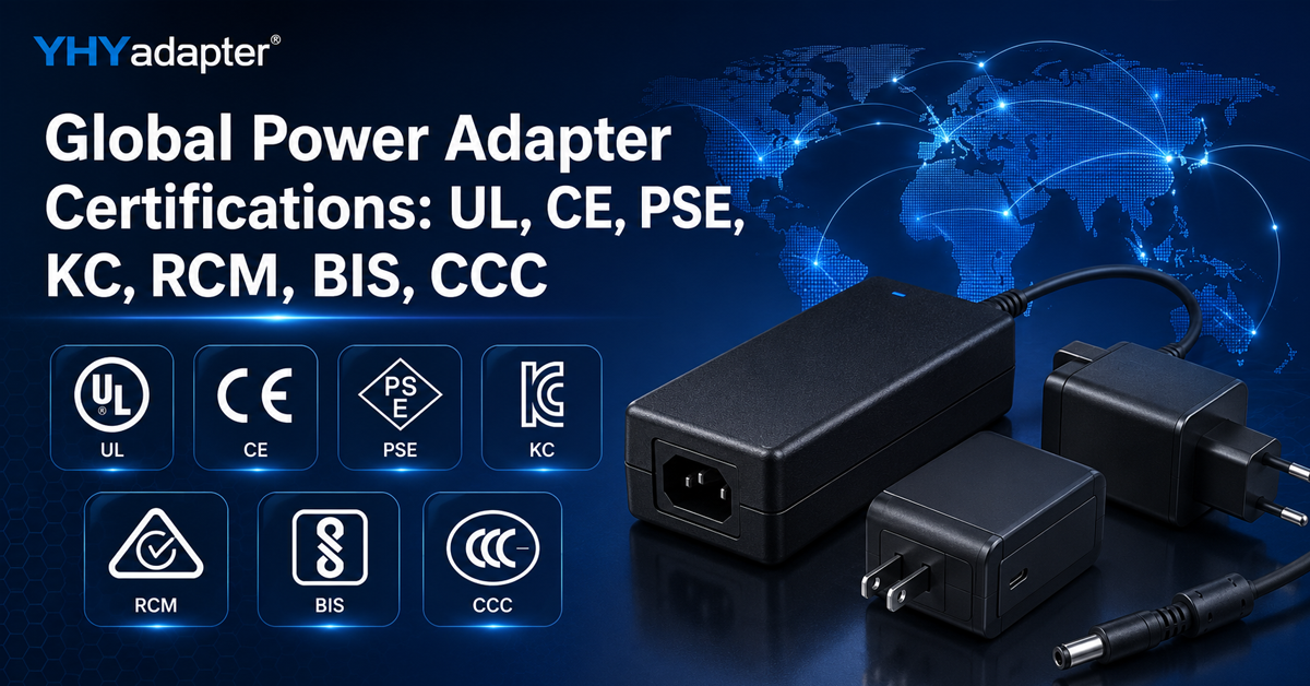
| USA | UL 8750 or UL 1310 (Class 2) | UL 8750 (LED equipment safety), UL 1310 (Class 2 power units), FCC Part 15 Subpart B | 8–14 wks (UL) |
| EU | CE conformity + EN 61347 series | EN 61347-1 (general), EN 61347-2-13 (LED DC/AC controlgear), EN 55015 (EMC lighting), EN 61000-3-2 (harmonics) | 2–6 wks (EMC + LVD) |
| China | CCC where in scope | GB 19510.1, GB 19510.14, GB/T 18595 (EMC lighting), GB 17625.1 (harmonics) | 4–6 wks |
| Japan | PSE depending on category | Appropriate PSE standard per product category | 4–9 wks |
| South Korea | KC safety + EMC | Applicable Korean lighting standards | 6–8 wks |
| Australia/NZ | RCM / EESS | AS/NZS 61347 series | 6–10 wks |
Available by model. Certification availability depends on product model, configuration, application requirements, and destination market. Not all options are available on every product model.
Key Standards Detail:
- UL 8750 is the primary safety standard for LED equipment in the US market, covering LED drivers, arrays, and controlgear.
- UL 1310 (Class 2) applies to power units with limited output power (≤100VA) and limited voltage (≤30Vrms/42.4Vpk). Class 2 certification simplifies wiring requirements in the US.
- EN 61347-2-13 is the EU safety standard for LED controlgear, the specific product standard for LED drivers.
- EN 55015 and EN 61547 are the EU EMC emission and immunity standards for lighting equipment.
Available by model. An adapter carrying UL 8750 and FCC Part 15 may support the end-product certification pathway. Final acceptance depends on the end-product construction, application, target market, and applicable certification program. For multi-market products, a driver with CB certification (IEC 61347-2-13 based) may facilitate streamlined national certification.
Why This Matters
- An LED driver certified to UL 62368-1 (IT/AV standard) may not be accepted for a UL 8750 (lighting) listing—the product standard must match the end-product classification.
- In the US, Class 2 certification (UL 1310) simplifies installation wiring because Class 2 circuits have fewer conduit and distance restrictions than Class 1 circuits.
- The EN 61347 series is distinct from the EN 62368-1 standard used for general power adapters. LED drivers for EU lighting applications must follow 61347.
What OEMs Should Do Now
- Confirm the product standard that applies to your luminaire type in each target market. LED drivers typically require lighting-specific standards (UL 8750, EN 61347) rather than general IT/AV standards.
- If designing for the US market, evaluate whether Class 2 (UL 1310) output characteristics are achievable for your power requirements—Class 2 simplifies luminaire certification and installation.
- Verify that the driver supplier holds the relevant certifications for your target markets before engaging in product development.
Q: Does a UL 62368-1 certified power adapter qualify for use in an LED luminaire sold in the US?
A: UL 62368-1 is the safety standard for IT/AV equipment. For LED luminaires, UL 8750 is typically required. A UL 62368-1 certified adapter may be accepted if the overall luminaire is evaluated to UL 8750 and the adapter falls within its scope, but the safest approach is to use a driver with UL 8750 certification.
Q: What is the difference between Class 2 and non-Class 2 LED drivers in the US?
A: Class 2 drivers (UL 1310) have limited output power (≤100VA) and require simpler wiring methods—no conduit needed for Class 2 circuits in most US installations. Non-Class 2 drivers require Class 1 wiring (conduit). Class 2 drivers also simplify the luminaire’s UL listing process because the output wiring is less restricted.
Useful Links
OEM Customization — CV AC/DC Power Adapters for LED Systems
LED lighting OEMs using a CV architecture may require power adapter modifications beyond catalog specifications. YHYadapter’s OEM/ODM customization capabilities for CV AC/DC adapters support several lighting-specific requirements.
Common customization considerations for CV power adapters used in LED systems:
- Cable length and connector type: Specifying output cable length, pre-stripped wires, or proprietary connectors for the luminaire’s wiring harness
- Output voltage adjustment: Subject to the electrical, thermal, protection, and certification limits of the selected platform
- Custom labeling and branding: OEM-specific labels with luminaire model number, electrical ratings, and regulatory marks
- Multi-output configurations: May be available depending on total power, rail requirements, platform architecture, engineering scope, MOQ, and certification requirements
- Dimming interface evaluation: May be evaluated depending on platform architecture, engineering scope, MOQ, and certification requirements
Minimum order quantities, lead times, and engineering NRE costs vary by customization type. Consult the YHYadapter engineering team for model-specific feasibility and pricing.
What OEMs Should Do Now
- Prepare a detailed power supply specification document: output voltage, current capacity, dimming requirements, IP rating, operating temperature range, mechanical dimensions, and target certifications.
- Identify which specifications are negotiable and which are hard requirements. Not all combinations are feasible—early engineering consultation is recommended.
- Request samples with the proposed customization for thermal and EMC testing in your luminaire before committing to production order quantities.
Q: Can YHYadapter produce a custom constant-voltage adapter with a specific output cable for LED strip lighting?
A: Custom cable length and connector type are standard OEM customization options for YHYadapter CV adapters. Contact the engineering team with your specific cable requirements.
Q: What is the typical lead time for a custom CV adapter with a proprietary output cable?
A: Lead time depends on the customization type. Standard catalog adapters with custom output cable length and labeling typically have shorter lead times than adapters requiring modified electrical specifications. Contact YHYadapter sales for a project-specific lead time.
Useful Links
CONCLUSION
Selecting the right LED lighting power architecture requires evaluating the output type (CC vs CV), dimming protocol compatibility, power quality requirements, thermal derating, IP rating needs, and certification pathways. For OEMs whose system uses a CV architecture—whether for LED strip lighting, signage, or as a regulated bus feeding integrated CC stages—YHYadapter offers regulated constant-voltage AC/DC power adapters with model-dependent support for output customization, cable configuration, and certification planning.
For applications requiring dedicated constant-current LED drivers, OEMs should evaluate products from specialized lighting driver manufacturers.
Related Resources
🔌 Related Products
📖 Related Guides
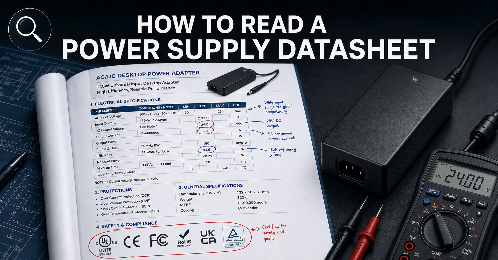
How to Read a Power Supply Datasheet
Learn how to evaluate connector specifications in a datasheet — current ratings, derating curves, certification verification.
🏭 Related Applications
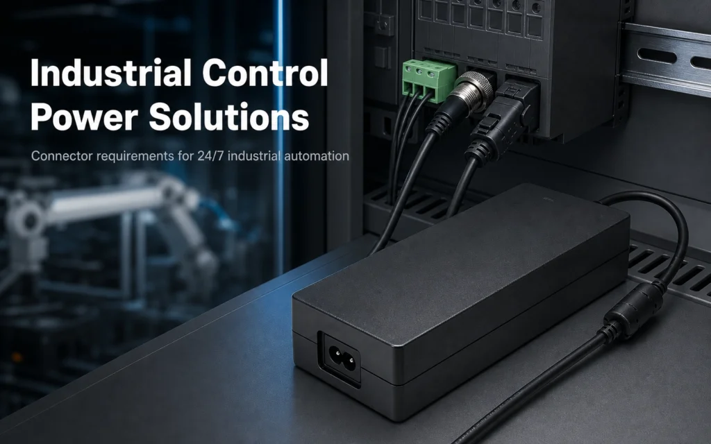
Industrial Control Power Solutions
Desktop power supplies designed for PLC panels, CNC controllers, and industrial automation systems.
✅ Related Certifications
UL 62368-1 Safety Certification
Safety standard covering connector creepage/clearance, temperature rise, and strain relief requirements for IT/AV equipment power adapters.