
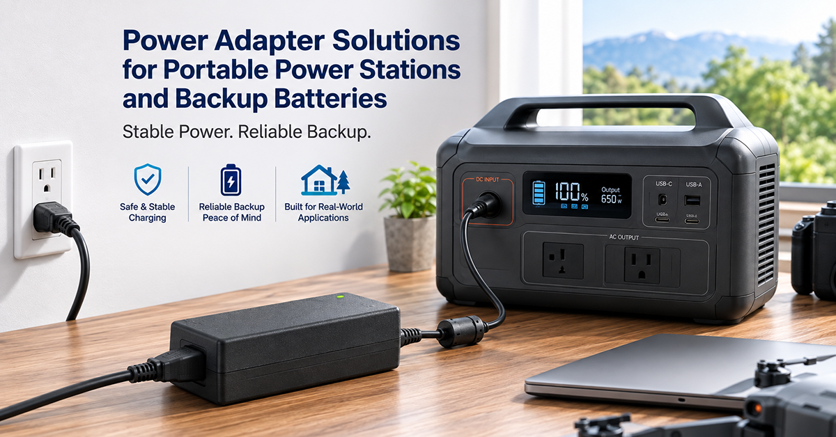
Portable power stations and battery backup systems are self-contained energy storage units that combine battery cells, a BMS, an AC inverter, DC outputs, and a charger in a single enclosure. The AC/DC charging input—the circuit that charges the internal battery from AC mains power—is a critical subsystem that determines how quickly the power station can be recharged, how much heat is generated during charging, and whether the charging process is safe and efficient.
This guide covers the power adapter and AC/DC charging circuit considerations for portable power stations and battery backup systems: charging input specifications, DC output regulation, inverter integration, thermal management, and OEM design guidance.
AC/DC Charging Input Design
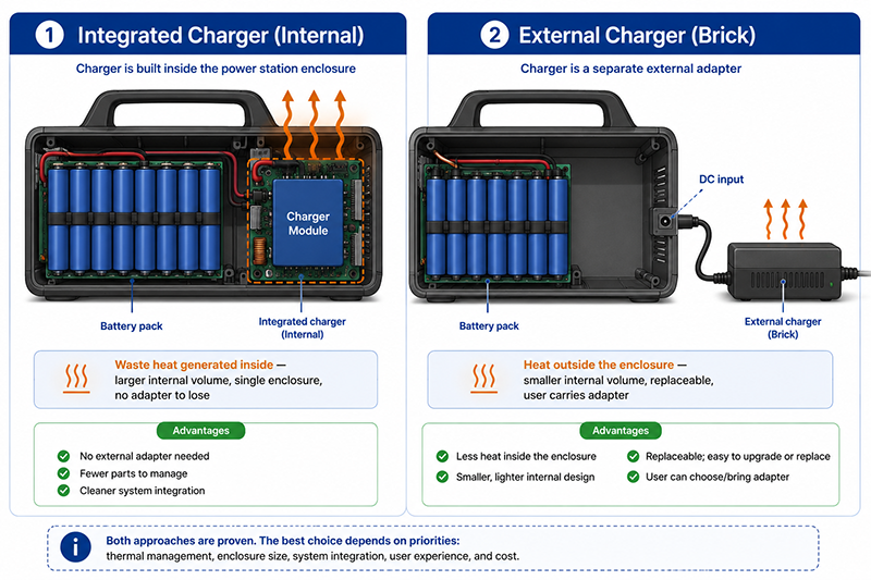
The AC/DC charging input converts AC mains power to the regulated DC voltage required to charge the internal battery. The charger can be integrated inside the power station enclosure or provided as an external adapter.
Integrated vs External Charger
| Approach | Advantages | Considerations |
|---|---|---|
| Integrated charger (internal) | Single enclosure, no external adapter to lose, simpler user experience | Waste heat generated inside the enclosure; larger internal volume |
| External charger (brick adapter) | Heat is outside the enclosure; smaller internal volume; replaceable | User must carry adapter; charging power limited by adapter rating |
| Integrated + external AC cord | AC cord connects directly to internal charger power supply | Similar to integrated; AC cord is simpler than DC brick |
Charging Power Requirements
| Power Station Capacity | Typical Battery Voltage | Recommended Charge Power | Charge Time (0–100%) | Adapter Rating |
|---|---|---|---|---|
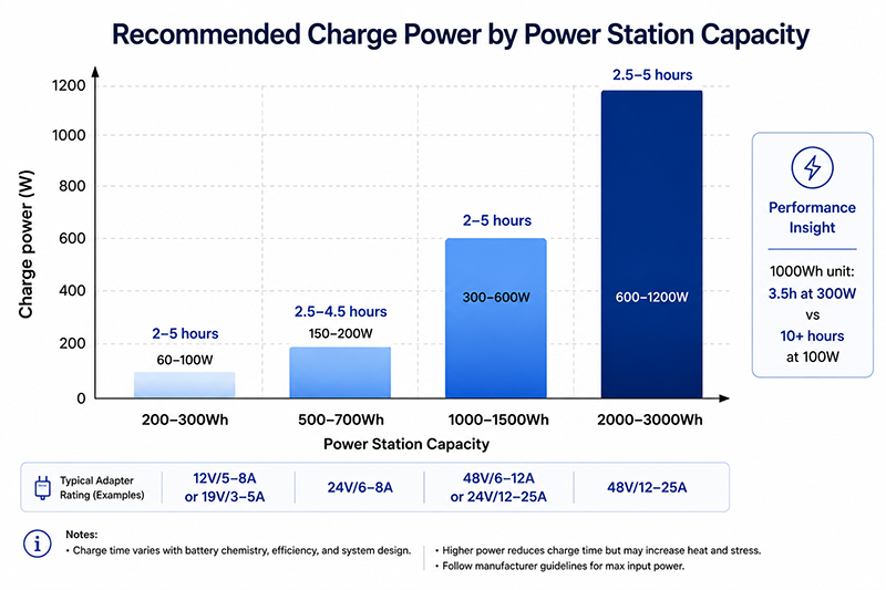
| 200–300Wh | 12V (3S Li-ion) | 60–100W | 2–5 hours | 12V/5–8A or 19V/3–5A |
| 500–700Wh | 24V (7S Li-ion) | 150–200W | 2.5–4.5 hours | 24V/6–8A |
| 1000–1500Wh | 48V (13S Li-ion) | 300–600W | 2–5 hours | 48V/6–12A or 24V/12–25A |
| 2000–3000Wh | 48V (16S LiFePO4) | 600–1200W | 2.5–5 hours | 48V/12–25A or higher |
Input Voltage Range
The AC/DC charger should accept universal input (100–240VAC, 50/60Hz) for global compatibility. Some portable power stations also accept DC charging from solar panels (MPPT input) and vehicle DC outlets (12V/24V from a car), requiring the charger or MPPT controller to prioritize or share the charging current.
Why This Matters
- Charging power determines recharge time. A 1000Wh power station charging at 300W recharges in approximately 3.5 hours (accounting for CV taper). At 100W, the same unit takes 10+ hours.
- Heat from the internal charger affects battery temperature, which can reduce charging efficiency and accelerate battery degradation. External chargers eliminate this thermal load.
- Multiple charging inputs (AC, solar, DC) require prioritization logic to prevent simultaneous charging from conflicting sources.
OEM Actions
- Determine the target charge time and calculate the required charging power. Balance charge time against the thermal constraints of the power station enclosure.
- For external chargers, specify an adapter with the correct charging profile (CC/CV for lithium batteries) and the appropriate connector for the power station.
- For integrated chargers, ensure the charger’s waste heat is managed through adequate ventilation or thermal coupling to the enclosure.
DC Output Regulation
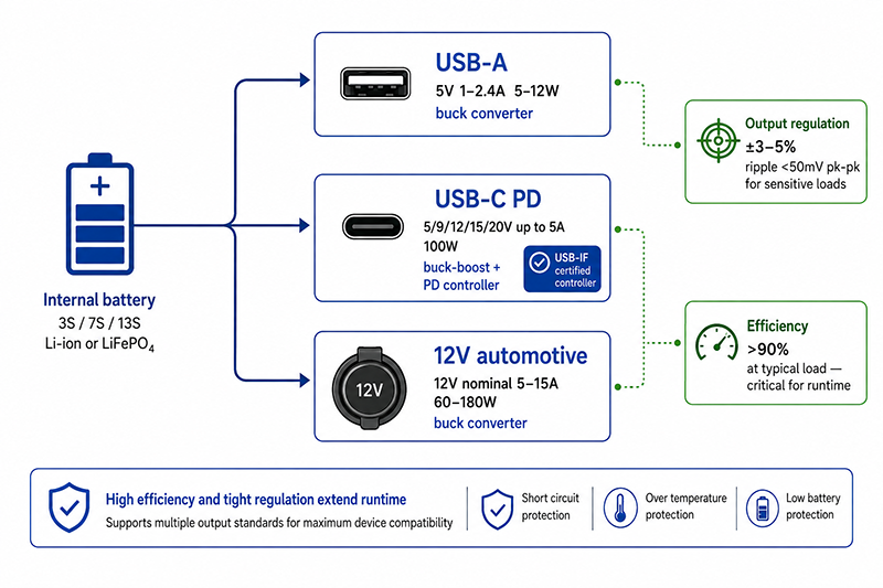
In addition to charging the battery, the power station must provide regulated DC output to power external devices. Common DC outputs include USB-A, USB-C PD, and 12V automotive-style outlets (cigarette lighter). Each output requires regulation from the battery voltage.
| DC Output Type | Voltage | Current | Power | Regulation Method |
|---|---|---|---|---|
| USB-A | 5V | 1–2.4A | 5–12W | Buck converter from battery voltage |
| USB-C PD | 5V, 9V, 12V, 15V, 20V | Up to 5A (100W) | Up to 100W | Buck-boost converter + PD controller |
| 12V automotive | 12V nominal | 5–15A | 60–180W | Buck converter from battery voltage |
| Adjustable DC output | Variable | Depends on design | Depends on design | Customer-specified regulation |
DC-DC Converter Requirements
| Parameter | Typical Requirement | Notes |
|---|---|---|
| Input voltage range | Full battery voltage range (depleted to full) | 3S: 9–12.6V; 7S: 21–29.4V; 13S: 39–54.6V |
| Output regulation | ±3–5% | Adequate for most DC-powered devices |
| Efficiency at expected load | >90% at typical load | Important for battery life (runtime) |
| Output ripple | <50mV pk-pk for sensitive loads | USB-C and audio equipment require clean power |
Why This Matters
- The DC outputs’ power consumption subtracts from the total battery capacity available for the AC inverter. Efficient DC-DC conversion is critical for maximizing runtime.
- USB-C PD requires a PD controller IC that negotiates voltage with the connected device. The controller must support the required PD profiles (5V, 9V, 12V, 15V, 20V at up to 5A for PD 3.0).
- The 12V automotive output is typically rated for 5–15A (60–180W). Higher current requires thicker wiring and larger connectors to avoid voltage drop.
OEM Actions
- Select DC-DC converters with >90% efficiency at the expected load range. A converter that is efficient at 50W but inefficient at 5W wastes battery capacity when powering small loads.
- For USB-C PD outputs, verify the PD controller is USB-IF certified and supports the required voltage/current profiles.
- Include overload protection (circuit breaker or resettable fuse) on the 12V automotive output to protect against short circuits or excessive load.
Thermal Management and Enclosure Design
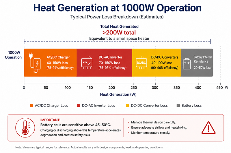
Thermal management is a critical design consideration for portable power stations because the AC/DC charger, AC inverter, and battery cells all generate heat within the same enclosure.
Heat Sources
| Component | Typical Efficiency | Power Loss (at 1000W) | Notes |
|---|---|---|---|
| AC/DC charger | 85–94% | 60–150W | Charging at 1000W input |
| DC-AC inverter | 85–93% | 70–150W | Inverting 1000W AC output |
| DC-DC converters | 90–96% | 40–100W | Output at 1000W total |
| Battery (internal resistance) | — | 20–50W | At 1000W discharge rate |
Thermal Design Strategies
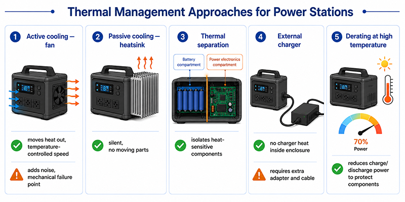
| Strategy | Benefit | Implementation |
|---|---|---|
| Active cooling (fan) | Moves heat out of enclosure | Fan with temperature-controlled speed |
| Passive cooling (heatsink) | No moving parts, silent | Large heatsink on charger and inverter |
| Thermal separation | Isolate heat-sensitive components | Compartment for battery vs power electronics |
| External charger | No charger heat inside enclosure | User-placed adapter dissipates heat externally |
| Derating at high temperature | Prevents component damage | Reduce charge/discharge power at elevated temperatures |
Why This Matters
- The total heat generated inside a portable power station at full charge and discharge can exceed 200W—equivalent to a small space heater. Without adequate thermal management, internal temperatures can rise above component ratings within minutes.
- Battery cells are sensitive to elevated temperature. Charging or discharging a lithium battery above 45–50°C accelerates degradation and creates safety risks.
- Active cooling (fan) adds noise, consumes battery power, and introduces a mechanical failure point. Passive cooling is preferred for silent operation and reliability.
OEM Actions
- Calculate the total heat generation under worst-case simultaneous charge and discharge. Verify the thermal design maintains component and battery temperatures within specified limits.
- For power stations with integrated chargers, consider active or passive cooling that prioritizes battery temperature over charger temperature.
- If using an external AC/DC charger, specify the charger’s operating temperature range and ensure it can operate at the maximum ambient temperature expected in the target market.
Useful Links
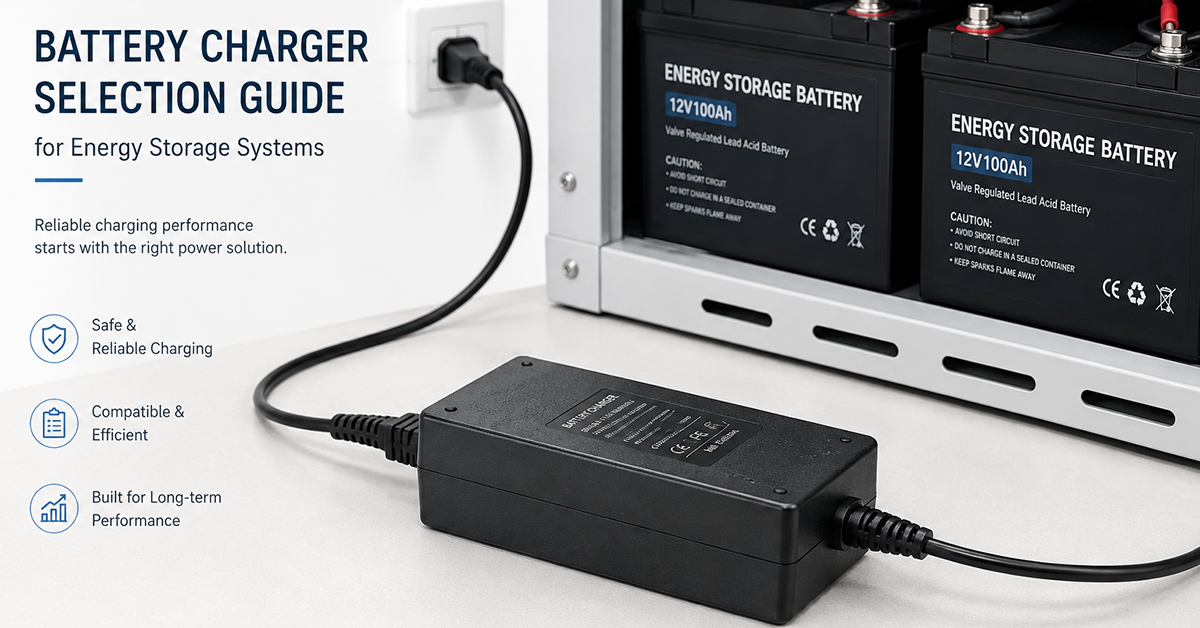
Related article: Battery Charger Selection Guide →
Related article: Charging Profiles Guide →
Related article: Power Adapter for Portable Power Stations →
Q: Can I use a standard laptop power adapter to charge a portable power station?
A: Many portable power stations accept DC input from a standard laptop-style adapter. The adapter must provide the correct voltage and have a current rating sufficient for the power station’s charging specification. However, standard laptop adapters are constant-voltage power supplies, not battery chargers—the power station’s internal charging circuit handles the CC/CV charging profile. Verify the input voltage range and connector compatibility.
Q: How fast can a portable power station charge from AC mains?
A: Charge time depends on the station’s battery capacity and the charger’s power rating. Typical charge times range from 1.5 hours (high-power charger, small capacity) to 8+ hours (low-power charger, large capacity). Many power stations support variable charging power to match different AC outlet capacities (e.g., 100W from a standard outlet, 600W from a high-power outlet).
Q: What is the typical efficiency of a portable power station’s AC charging circuit?
A: The total AC-to-battery efficiency (AC input to battery energy stored) is typically 80–90%, depending on the charger architecture. LLC resonant converters achieve the higher end of this range. An additional 5–10% loss occurs in the DC-AC inverter when converting battery power back to AC output.
Conclusion
AC/DC power solutions for portable power stations and battery backup systems involve three key subsystems: the charging input (AC/DC converter), DC output regulation (USB, 12V), and thermal management of all power components within the enclosure. The charger can be integrated or external, with each approach offering trade-offs in heat management, portability, and user experience. Selecting the correct charging power, DC output regulation architecture, and thermal design determines the power station’s charge time, runtime, and reliability.
Related Resources
🔌 Related Products
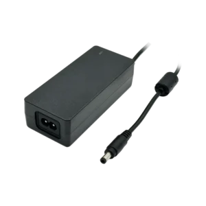
12.6V 4A 50W Li-Ion Charger (3-series Li-Ion charging)
12.6V 4A CC/CV Li-Ion charger for 3-series battery packs
🏭 Related Applications
📖 Related Guides
✅ Related Certifications
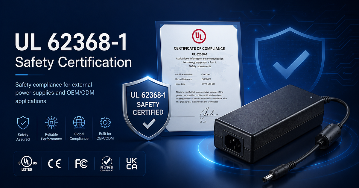
UL 62368-1 Safety Certification
Safety standard covering connector creepage/clearance, temperature rise, and strain relief requirements for IT/AV equipment power adapters.