
Introduction
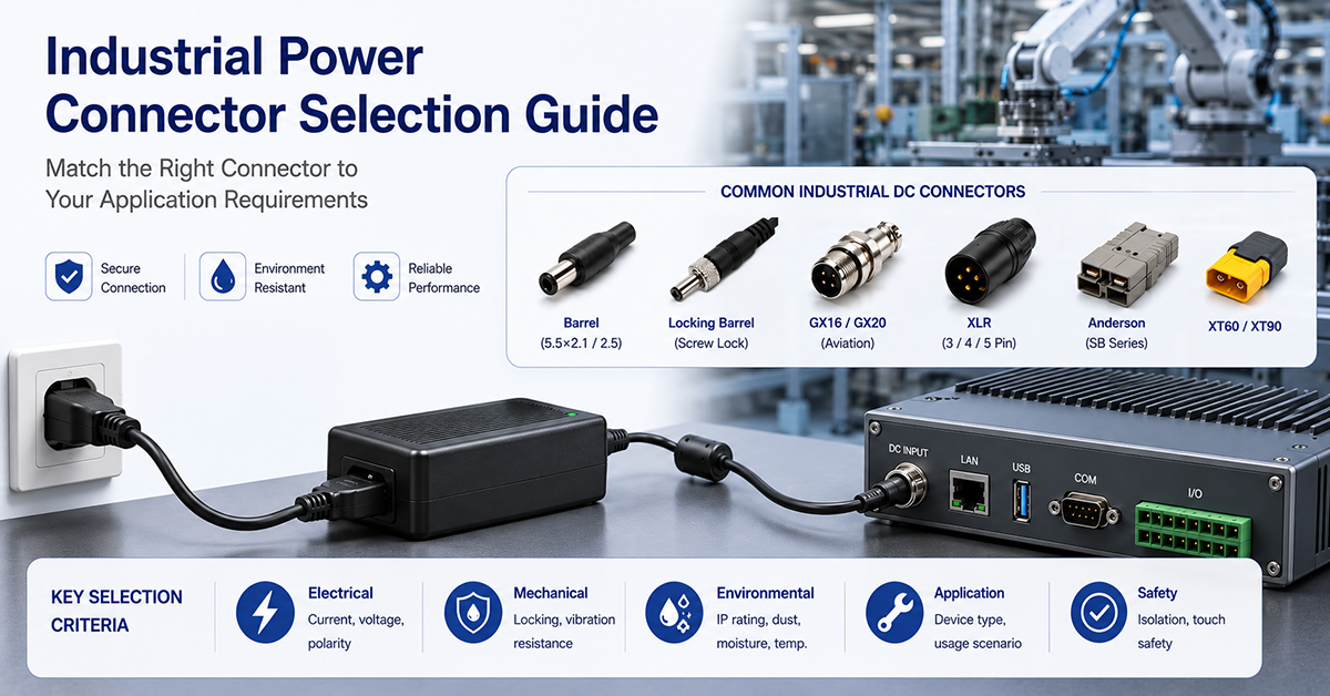
Connector selection in industrial power systems is a reliability decision, not just a specification exercise. The wrong connector — or the right connector used incorrectly — is one of the most common failure points in industrial equipment. Vibration loosens contacts, dust degrades insulation, moisture causes corrosion, and mismatched connectors create intermittent faults that are notoriously difficult to diagnose.
This guide covers connector selection for industrial power applications: which connector types work best in which scenarios, how environment and vibration affect connector choice, and how to maintain connectors for long-term reliability.
⚠️ This article focuses on industrial connector DECISIONS. For general connector types, definitions, and specifications, see The Complete OEM Guide to DC Power Connector Types (PF04).
Industrial Connector Types — Decision Guide
The following sections explain which connector types are most suitable for industrial power applications and why. For specification data (current ratings, pin configurations, dimensions), refer to the connector datasheet.
Terminal Blocks
Terminal blocks are the backbone of control cabinet wiring. The three primary mechanisms differ significantly in industrial suitability.
| Type | Retention Strength | Installation Speed | Vibration Resistance | Reconnection Cycles |
|---|---|---|---|---|
| Screw terminal | High | Moderate | Good (with torque control) | 50–100 |
| Spring-cage (cage clamp) | High | Fast | Excellent (gas-tight) | 100–200+ |
| Push-in | Moderate | Fastest | Good (solid/ferruled wire) | 10–50 |
Screw terminal provides the highest mechanical retention force when properly torqued. The main failure mode is loosening from thermal cycling or vibration — which is why torque-controlled screwdrivers or pre-coated screws are recommended for high-vibration environments.
Spring-cage connection uses a stainless steel spring that maintains constant pressure on the conductor regardless of thermal expansion or contraction. This makes it inherently vibration-resistant. The gas-tight connection also prevents oxidation at the contact point — critical for long-term reliability in industrial environments.
Push-in is the fastest to install — simply insert a solid or ferruled wire. It’s suitable for lower-current signals and power connections in controlled environments. Not recommended for high-vibration locations or frequent reconnection.
Industrial recommendation: Prefer spring-cage terminal blocks for vibration-prone installations. Use screw terminals with torque control for high-current connections. Limit push-in to non-critical, low-current circuits in clean environments.
GX Connectors (Standard Circular)
GX connectors are circular connectors available in standard sizes (GX12, GX16, GX20, GX25) with pin counts from 2 to 19+. They offer a good balance of current capacity, size, and cost for panel-to-panel or panel-to-device connections.
Key selection factors in industrial environments:
– Coupling: Threaded coupling (GX) provides better vibration retention than bayonet (GY) or snap-lock
– Pin configuration: Higher pin counts at the same shell size reduce current per pin — verify derating when all pins carry current simultaneously
– Sealing: Standard GX connectors are not IP-rated. For environments requiring IP protection, specify sealed versions with O-rings or gasket panels
Best for: Panel interconnections, sensor-to-controller links, and internal cabinet wiring where occasional disconnection is needed.
Locking DC Connectors
Standard barrel jacks (2.1mm, 2.5mm center pin) are notorious for accidental disconnection in industrial environments. Locking variants solve this with a threaded collar that secures the connector to the mating receptacle.
Why locking matters in industrial:
– A machine vibration of 1g at 50Hz can generate forces that eject a standard barrel connector
– Accidental disconnection during operation causes unplanned machine stops
– Locking connectors provide ≥5× the retention force of standard barrel jacks
Keying options: Offset center pin positions prevent cross-connection between different voltage supplies in multi-voltage systems. A 24V system might use a 2.5mm offset pin, while a 12V system uses a 2.1mm center pin.
Best for: DC power input on industrial equipment where vibration is present — PLCs, HMIs, actuators, and field devices.
M12 Connectors (IEC 61076-2-101)
M12 connectors are the standard for field-level device connection in industrial automation. Their IP65/IP67 rating and coding system make them suitable for direct use in harsh environments.
Coding and application:
| Code | Pin Count | Application | Typical Power |
|---|---|---|---|
| A-coded | 3, 4, 5, 8 | Sensors, actuators, general DC power | ≤4A per pin |
| B-coded | 4, 5 | Profibus, fieldbus networks | Signal only |
| D-coded | 4 | Industrial Ethernet (100 Mbps) | PoE up to 15.4W |
| S-coded | 4 | AC power distribution | 630V/12A |
| T-coded | 4 | DC power distribution | 63V/12A |
| X-coded | 8 | Gigabit Ethernet (1 Gbps) | PoE+ up to 30W |
Selection rule: Use A-coded for general DC sensor/actuator power. Use S-coded or T-coded for higher-power distribution where A-coded pins would be current-limited. Use X-coded for high-speed data + power (PoE+).
Environmental advantage: M12 connectors are sealed when mated (IP65/IP67). They withstand wash-down environments, dust, and temporary immersion — making them the preferred choice for food processing, automotive manufacturing, and outdoor automation.
M8 Connectors
M8 connectors are physically smaller than M12 (8mm thread vs 12mm) and carry lower current ratings. They’re designed for compact sensors where space is limited.
Key differences from M12:
– Current rating: ≤3A per pin (vs ≤4A for M12 A-coded)
– Pin count: 3 or 4 pins typically
– Mechanical robustness: Less robust than M12 — more susceptible to damage from impact or over-torquing
– IP rating: IP65/IP67 when mated (same as M12)
Best for: Miniature sensors, compact actuators, and devices where M12 connectors would be physically too large.
Anderson Power Connectors
Anderson connectors (SB/SBS series) are high-current, genderless connectors commonly used in battery-powered and high-current industrial systems.
| Series | Current Rating | Typical Applications |
|---|---|---|
| SB50 | 50A | Battery chargers, medium equipment |
| SB120 | 120A | Large battery systems, floor machines |
| SB175 | 175A | Industrial vehicles, UPS systems |
| SBS50 | 50A (compact) | Space-constrained high-current |
| SBS75 | 75A (compact) | EV chargers, industrial tools |
Industrial advantages:
– Genderless design — any two connectors of the same series mate, regardless of being “plug” or “receptacle”
– Color-coded housings for voltage identification (red 12V, blue 24V, yellow 48V, gray 72V)
– Touch-safe contacts — no exposed live parts
– Blind-mate capability — forgiving of misalignment during connection
Best for: High-current distribution, battery connections, industrial vehicle power, and any application requiring frequent, high-current connection/disconnection.
Industrial Cable Assemblies (Pre-Wired)
Pre-wired cable assemblies combine a connector with a cable in a factory-molded unit. They’re increasingly preferred over field-attachable connectors for industrial applications.
| Aspect | Factory-Molded | Field-Attachable |
|---|---|---|
| IP rating | Full (IP65–IP68) | Reduced (seal may be compromised) |
| Reliability | High (consistent quality) | Variable (dependent on installer skill) |
| Cost per unit | Higher | Lower |
| Installation time | Minimal (plug and play) | Higher (cable prep + assembly) |
| Field modification | Not possible | Flexible (cut to length, custom routing) |
Rule of thumb: Use pre-wired assemblies for connections exposed to wash-down, dust, or vibration. Use field-attachable for custom cable lengths, tight conduit runs, or where connector replacement is expected.
Environmental Considerations
Connector selection must account for the physical environment. A connector’s electrical rating is meaningless if it fails mechanically.
Vibration Resistance
Vibration loosens mechanical connections through repeated micro-motion at the contact interface. This increases contact resistance, generates heat, and eventually causes failure.
Vibration levels (IEC 60068-2-6):
| Severity | Acceleration | Typical Environments | Connector Requirement |
|---|---|---|---|
| Light | 0.35g | Control cabinets, clean areas | Standard locking mechanism |
| Moderate | 2g | Factory floor, conveyors | Threaded or bayonet lock |
| Severe | 5g+ | Near heavy machinery, vehicles | Threaded lock + secondary retention |
Connector retention by locking type:
| Locking Type | Vibration Rating | Typical Applications |
|---|---|---|
| Friction-only | Poor | Bench equipment, non-vibrating |
| Snap-lock | Fair | Light to moderate vibration |
| Bayonet | Good | Moderate to medium vibration |
| Threaded | Excellent | Severe vibration, critical connections |
| Threaded + secondary clip | Best | Transportation, heavy industry |
Secondary retention methods:
– Cable ties securing connector body to bracket
– Locking clips on M12 connectors
– Bracket-mounted receptacles with strain relief
– Conduit-sealed connections for permanently wired installations
IP Rating for Connectors
An IP (Ingress Protection) rating indicates a connector’s resistance to solids and liquids. The rating applies only when the connector is fully mated.
| IP Rating | Solids | Liquids | Industrial Application |
|---|---|---|---|
| IP20 | Fingers (≥12.5mm) | None | Control cabinet interior (dry, clean) |
| IP54 | Limited dust | Splashing water | Light industrial, sheltered |
| IP65 | Dust-tight | Water jets | Factory floor, wash-down areas |
| IP67 | Dust-tight | Temporary immersion | Outdoor, wet environments |
| IP68 | Dust-tight | Continuous immersion | Submersible equipment |
Important: An unmated IP67 connector has no ingress protection. Always use dust caps on unmated receptacles in dusty or wet environments.
Material considerations for IP-rated connectors:
– Sealing gaskets/O-rings degrade over time — silicone gaskets last longest
– Brass or stainless steel shells resist corrosion better than plastic in wash-down environments
– Plastic connectors (PUR, TPE-U) are lighter and chemical-resistant but less UV-stable
Panel Wiring Best Practices
Cable entry: Cable glands for individual cables, bulkhead-mounted receptacles where panel disconnection is needed, or direct hardwired entry through a knockout.
Wire dressing rules:
– Segregate power and signal wiring (minimum 50mm separation recommended)
– Maintain minimum bend radius: 4× cable OD fixed, 6× flexible
– Secure cables within 100mm of each connector to prevent lever forces on the contact
Strain relief — three levels: internal (cable tie/clamp inside the enclosure), external (cable gland at enclosure entry), and system (cable tray or conduit absorbing tension before the panel).
Maintenance and Inspection
Regular connector inspection prevents unplanned downtime. The frequency depends on the environment severity.
Inspection Intervals
| Environment | Visual Inspection | Torque/Resistance Check | Full Replacement |
|---|---|---|---|
| Clean indoor cabinet | Annually | Every 3 years | Every 5–7 years |
| Moderate industrial | Every 6 months | Annually | Every 3–5 years |
| Harsh (dust, vibration) | Quarterly | Every 6 months | Every 1–3 years |
| Extreme (wash-down, outdoor) | Monthly | Quarterly | Annually or per fault |
Connector Wear Indicators
| Indicator | What It Means | Action |
|---|---|---|
| Contact resistance > 1.5× initial | Contact degradation or oxidation | Clean or replace |
| Visible corrosion (green/white deposits) | Chemical attack or moisture ingress | Replace immediately |
| Mechanical looseness (torque reduction) | Spring fatigue or thread wear | Retorque or replace |
| Discoloration or melting marks | Overheating — contact resistance or overload | Replace + investigate cause |
| Seal cracking or hardening | Gasket/O-ring aging | Replace seal |
| Mating force significantly changed | Contact wear or housing deformation | Replace connector pair |
Cleaning Procedures
- Isopropyl alcohol (≥90%) on a lint-free cloth — the standard industrial method
- Contact cleaner sprays — effective, but verify plastic compatibility first
- Avoid: abrasive pads (remove plating), petroleum-based solvents (attack plastics), and compressed air at close range (forces contaminants into contacts)
- Inspect and re-lubricate O-rings with silicone grease after cleaning, if specified by the manufacturer
Replacement Triggers
Replace connectors when any of the following conditions are met:
- Contact resistance exceeds 1.5× the initial (as-measured) value
- Visible corrosion on contact surfaces
- Seal damage — cracks, tears, permanent compression set
- Mating force degradation — too loose or requiring excessive force
- Specified mating cycle limit reached, or any physical damage (cracks, deformation, broken locking tabs)
Selection Decision Framework
Use this step-by-step framework to select connectors for any industrial power application.
Step 1 — Define power requirements:
– Voltage (DC or AC?)
– Current (continuous and peak)
– Number of conductors (power + signal + ground?)
Step 2 — Define environmental conditions:
– Vibration severity (light / moderate / severe)
– IP rating required (IP20 / IP54 / IP65 / IP67+)
– Temperature range (min/max ambient)
– Chemical exposure (oil, coolant, solvents)
Step 3 — Define mechanical requirements:
– Mating cycle lifetime (1,000 / 5,000 / 10,000+)
– Installation constraints (panel cutout size, cable routing)
– Mating/unmating frequency (daily / weekly / install-only)
Step 4 — Match to connector type:
| Scenario | Recommended Connector |
|---|---|
| Cabinet wiring, permanent | Terminal block (spring-cage) |
| Field device, moderate vibration | M12 A-coded (sensors/actuators) |
| Field device, high power | M12 T-coded or S-coded |
| Equipment DC input, vibration present | Locking DC connector |
| High-current, frequent connect | Anderson (SB/SBS series) |
| Compact sensor, space-limited | M8 connector |
| Outdoor, wash-down environment | M12 or pre-wired assembly, IP67+ |
Step 5 — Verify against standards:
– UL 508 / UL 61010 for industrial control panels
– IEC 61076-2-x for M8/M12 connector types
– NEMA ratings for North American installations
Step 6 — Cross-reference specifications:
– Confirm pinouts, mechanical drawings, and detailed ratings against the connector datasheet
– Verify connector compatibility with YHYadapter products
Recommended YHYadapter Products
| Product | Standard Connector | Available Options |
|---|---|---|
| YHY-24002500 (60W) | Locking DC 2.5mm | Terminal block, custom M12 |
| YHY-24005000 (120W) | Locking DC | Terminal block, M12 A-coded available |
| Available by model (240W) | Locking DC + terminal block | Anderson custom option, M12 T-coded |
| Custom OEM | Any connector per specification | Full custom connector integration |
YHYadapter offers custom connector integration for OEM programs, per OEM specification. Specify your connector type, pinout, cable length, and IP rating when requesting a quote.
Related Resources
- PF04 — The Complete OEM Guide to DC Power Connector Types — General connector knowledge (connector types, definitions)
- IA11 — Choosing Power Adapters for Harsh Industrial Environments — Connectors in extreme conditions
- IA09 — Industrial Power Protection Design — Protection coordination in connector circuits
- IA01 — How to Choose the Right Power Adapter for Your Industrial Application — Cluster gateway
- IA06 — 24V Industrial Power Supply Selection Guide — Enable link after IA06 is live
- Industrial Application Hub — /industrial-control-power-solutions/
CTA: Specify Connector Requirements in Your RFQ | Browse Connector Options | Request Custom Connector Integration