
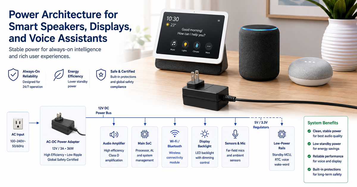
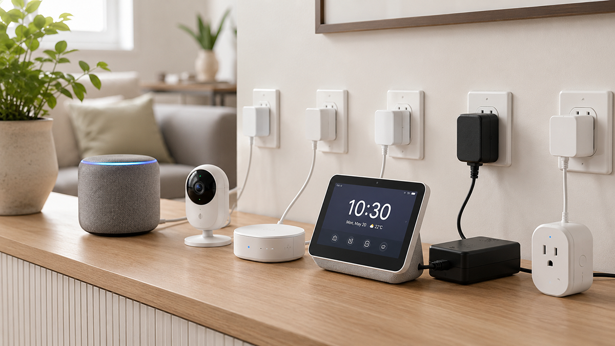
Smart speakers, smart displays, and voice assistants combine multiple power-demanding subsystems in a single compact enclosure: an audio amplifier and speaker driver, a display panel and backlight (in smart displays), a microphone array for voice capture, wireless connectivity (Wi-Fi, Bluetooth), and a main processor for voice processing and application logic. Each subsystem has different power requirements, and the interactions between them—particularly the need for clean power on the microphone array while the amplifier draws transient peaks—make power architecture design a critical aspect of product development.
This guide covers power architecture considerations for smart speakers, displays, and voice assistants: subsystem power requirements, noise isolation between audio capture and playback, display power management, and external adapter selection.
Subsystem Power Requirements
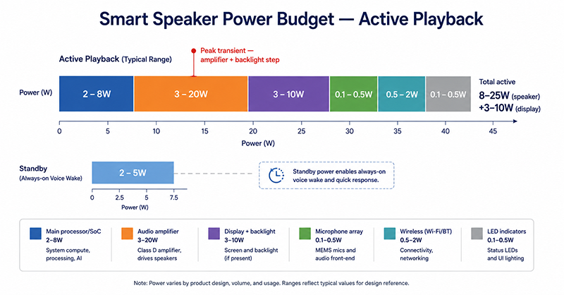
A typical smart speaker or smart display contains the following power-consuming subsystems:
| Subsystem | Typical Power Range | Voltage Requirements | Noise Sensitivity |
|---|---|---|---|
| Main processor / SoC | 2–8W | 3.3V, 1.8V, 1.2V (core) | Low (digital) |
| Audio amplifier | 3–20W (dependent on output power) | 12V, 24V or direct from adapter | Low to moderate (PSRR depends on amplifier) |
| Display panel + backlight (smart displays) | 3–10W | 3.3V (panel), 12–24V (backlight LED) | Low to moderate |
| Microphone array (2–7 mics) | 0.1–0.5W | 3.3V, 1.8V (analog and digital) | High (affects voice capture quality) |
| Wireless (Wi-Fi + BT) | 0.5–2W (active), 0.01–0.1W (idle) | 3.3V, 1.8V | Low |
| LED indicators | 0.1–0.5W | 3.3V or 5V | Low |
Total System Power
A typical smart speaker without a display consumes 8–25W during active use (music playback) and 2–5W in standby (always-on voice wake). A smart display adds 3–10W for the display and backlight. External adapters in the 12–36W range are common for smart speakers, and 24–60W for smart displays.
Why This Matters
- The amplifier and display backlight draw the majority of the power budget. The microphone array and wireless modules draw relatively little power but have the highest noise sensitivity.
- The power budget must account for all subsystems operating simultaneously: music playback with display on, voice capture active, and Wi-Fi connected.
- The peak power demand (amplifier transient, display brightness step change) determines the adapter’s required current capability, not just the average power.
What OEMs Should Do Now
- Create a power budget that includes all subsystems at their maximum simultaneous operating condition.
- Determine the peak transient current demand (amplifier output + display backlight step + processor burst) and verify the adapter can deliver this within its transient capability.
- Select an adapter voltage that minimizes conversion losses across all subsystems. A 12V or 24V adapter is common, with onboard DC-DC converters generating the required lower voltages.
Noise Isolation Between Microphone Array and Amplifier
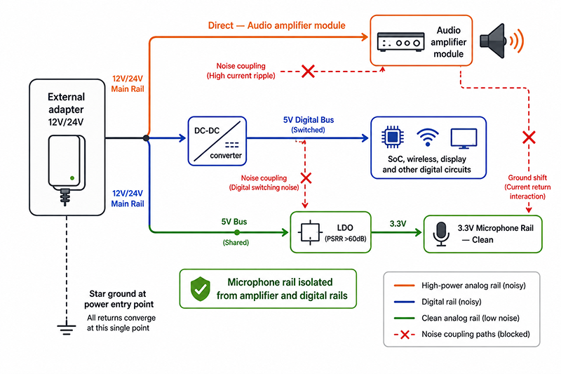
Coupling Paths
| Path | Mechanism | Mitigation |
|---|---|---|
| Conducted through power rail | Amplifier current draw creates ripple on shared power rail | Separate regulators for microphone and amplifier rails |
| Ground shift | Amplifier current through shared ground impedance | Star grounding at power entry point |
| Radiated from amplifier inductor | Magnetic field from Class-D output inductor couples into microphone traces | Physical separation; magnetic shielding; PCB layout |
| Radiated from speaker cable | Speaker current creates magnetic field | Twisted pair speaker cable; routing away from microphone |
Power Rail Partitioning
| Rail | Supplied By | Noise Requirement |
|---|---|---|
| Microphone (analog) | Low-noise LDO from adapter or main regulated rail | <10µV RMS noise typical |
| Microphone (digital PDM) | LDO from adapter or main rail | <50µV RMS |
| SoC / processor | DC-DC converter (efficient) | 10–50mV ripple acceptable |
| Amplifier | Direct from adapter or DC-DC | 50–150mV ripple acceptable |
| Display backlight | DC-DC boost converter | 20–100mV ripple (visible as flicker if poorly filtered) |
Design Strategy
A recommended architecture is to use the external adapter’s output as the main power bus, then generate individual rails:
- Adapter output (12V or 24V) → Direct to amplifier module
- Adapter output → DC-DC converter → 5V bus for digital circuits
- 5V bus → LDO → 3.3V for microphone array (clean)
This approach keeps the microphone rail separate from the amplifier and digital rails, with the LDO providing >60dB PSRR at audio frequencies.
Why This Matters
- Voice assistant performance depends on the microphone’s ability to capture quiet voice commands while the speaker is playing music at high volume. Power supply noise on the microphone rail directly degrades voice capture range.
- A microphone array with inadequate power supply filtering may require the user to speak 2–3× louder for reliable voice capture during music playback.
- The amplifier’s ground current can shift the microphone ground reference by millivolts, which is significant relative to microphone signal levels (tens of millivolts).
What OEMs Should Do Now
- Partition the power architecture with separate regulators for the microphone array, processor, and amplifier. Use LDOs for microphone rails for the best noise rejection.
- In PCB layout, keep the microphone power and ground traces physically separate from the amplifier and processor traces. Use a star ground topology at the power entry point.
- Test voice capture performance during simultaneous music playback to verify noise isolation. Measure microphone rail noise with an oscilloscope during worst-case amplifier load.
Display Power Management (Smart Displays)
Display Subsystem Power
| Display Size | Panel Type | Typical Backlight Power | Typical Total Display Power |
|---|---|---|---|
| 5–7 inch | LCD | 2–5W | 3–7W |
| 8–10 inch | LCD | 4–8W | 5–10W |
| 10+ inch | LCD | 6–12W | 8–15W |
Backlight Voltage
LED backlights typically require 12–24V, generated by a boost converter from the main power rail. The boost converter’s switching frequency should be selected to avoid interference with the display timing and the microphone array.
Power Management States
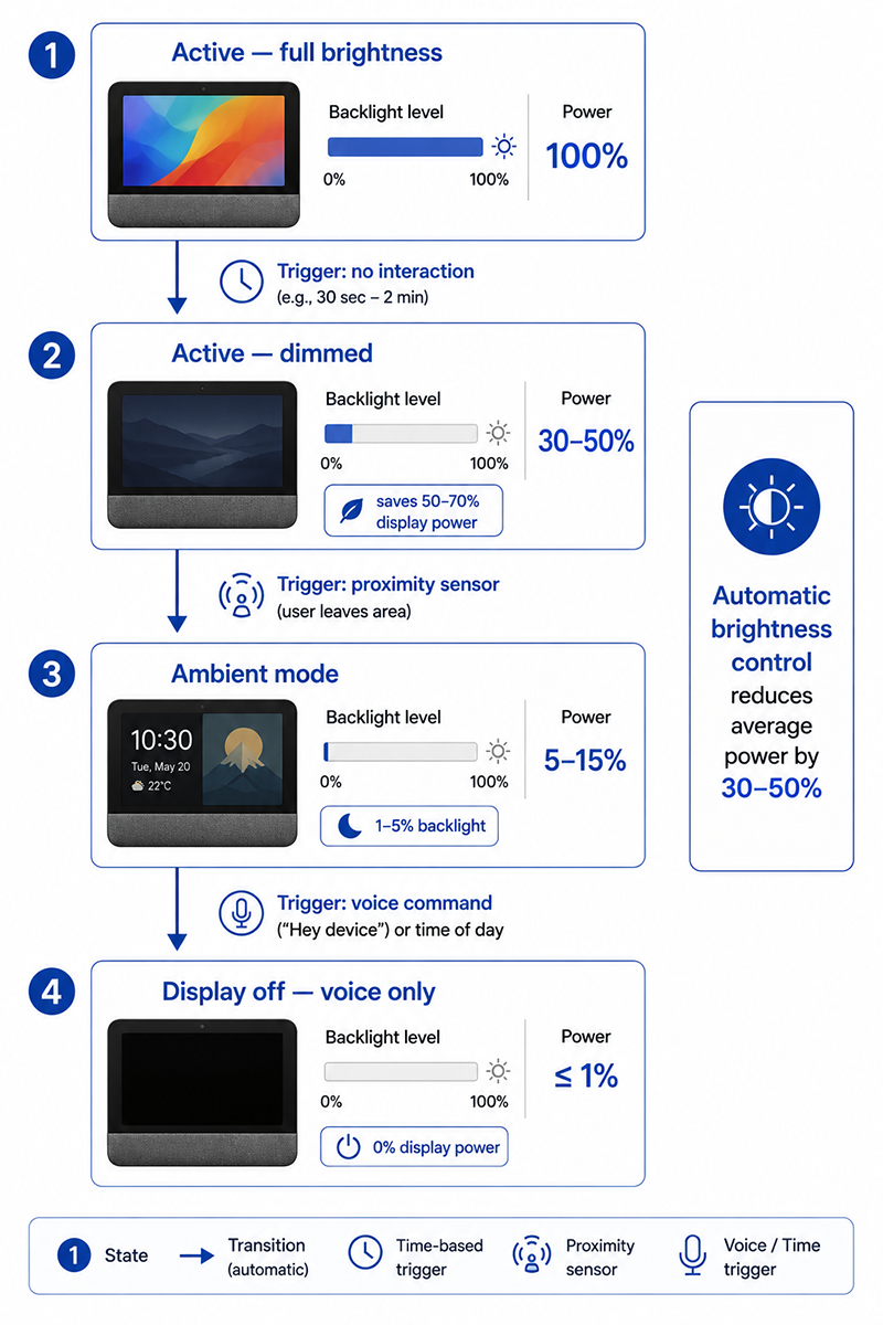
Smart displays benefit from multiple power states that manage display power based on user interaction:
- Active (display on, full brightness): Display at maximum power
- Active (display on, dimmed): Backlight reduced to 10–30%, saving 50–70% of display power
- Ambient mode (display on, low brightness): Backlight at 1–5%, content simplified (clock, artwork)
- Display off (voice-only): Display backlight off, saving full display power
Why This Matters
- The display backlight is the largest power consumer in a smart display after the audio amplifier. Managing backlight brightness based on ambient light and user activity can reduce average power by 30–50%.
- The backlight boost converter’s switching noise can couple into the microphone or wireless circuits if not properly filtered or shielded.
- A smart display in ambient mode (clock/artwork display) may consume 5–10W, compared to 15–25W in active video playback.
What OEMs Should Do Now
- Design the backlight boost converter with appropriate switching frequency and output filtering to avoid interference with the display, microphone, and wireless modules.
- Implement automatic brightness control based on ambient light sensor input. Reduce backlight to minimum when no user interaction is detected.
- Include a display-off (voice-only) mode that can be activated by voice command or proximity sensor.
External Adapter Selection
Adapter Selection Criteria
| Criterion | Typical Requirement | Notes |
|---|---|---|
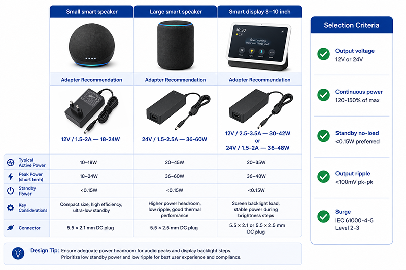
| Output voltage | 12V or 24V | 12V is common for speakers ≤30W; 24V for higher power or smart displays |
| Continuous power | 120–150% of calculated maximum | Derating for continuous operation |
| Standby no-load | <0.15W preferred | Contributes to device standby power |
| Output ripple | <100mV pk-pk (moderate) | Microphone isolation via onboard LDO covers adapter ripple |
| Surge protection | IEC 61000-4-5 Level 2–3 | AC-powered connected home device |
| Certification | UL/CE/FCC for target markets | Available by model |
Common Adapter Ratings
- Small smart speaker (no display): 12V / 1.5–2A (18–24W)
- Large smart speaker: 24V / 1.5–2.5A (36–60W)
- Smart display (8–10 inch): 12V / 2.5–3.5A (30–42W) or 24V / 1.5–2A (36–48W)
Why This Matters
- A 12V adapter is suitable for speakers up to approximately 30W system power. Beyond this, 24V reduces the current for the same power, lowering I²R losses in the adapter and cabling.
- The adapter must be selected for continuous operation at the maximum simultaneous load (music + display + voice + wireless), not average power.
- A low-standby adapter (<0.15W no-load) helps the device meet standby power regulations while keeping the voice wake circuit active.
What OEMs Should Do Now
- Calculate the maximum continuous power requirement and select an adapter rated for at least 120% of this value.
- Specify adapter output voltage based on the amplifier’s requirements and the power level. Choose 24V for systems above 30W to reduce current.
- Request no-load power data from the adapter supplier and verify the adapter contributes ≤0.15W to the device’s standby power.
Q: Can a smart speaker use the same power rail for the amplifier and the microphone array?
A: Directly powering the microphone array from the same rail as the amplifier is not recommended because amplifier current transients create voltage ripple and ground noise that couple into the microphone circuits. The microphone array should be powered from a separate low-noise LDO, isolated from the amplifier rail.
Q: What is the best adapter voltage for a smart display with a 10-inch LCD?
A: 24V is a common choice for smart displays with 10-inch or larger screens. The higher voltage reduces current for the same power, and 24V directly powers many display backlight boost converters without additional conversion. For smaller displays (5–8 inch), 12V is typically sufficient.
Q: How much standby power is acceptable for a voice assistant that needs to listen continuously?
A: Always-on voice wake typically requires 1–3W total, including the microphone array, audio codec, wake-word processor, and wireless connectivity. EU 2023/826 limits standby to 0.50–0.80W for most devices, but voice assistants with always-on listening may qualify for higher limits under the “networked standby” provisions. Verify the applicable classification for the specific device type and market.
Conclusion
Smart speakers, smart displays, and voice assistants combine multiple power-sensitive subsystems in a single product. The power architecture must manage the conflicting requirements of the high-current amplifier, low-noise microphone array, processor, wireless module, and display backlight. Key design strategies are: partitioning the power rails with separate regulators, using LDOs for microphone power isolation, implementing display backlight power management, and selecting an external adapter rated for continuous operation at 120–150% of the calculated maximum power.
Related Resources
🔌 Related Products
🏭 Related Applications
📖 Related Guides
✅ Related Certifications
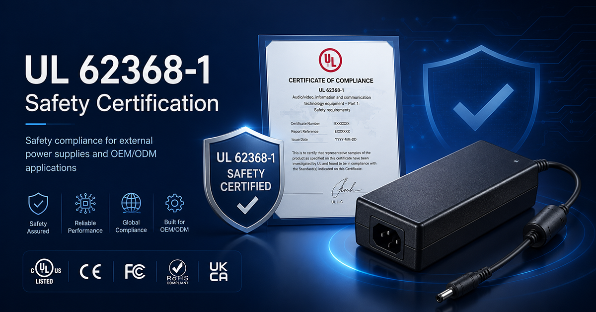
UL 62368-1 Safety Certification
Safety standard covering connector creepage/clearance, temperature rise, and strain relief requirements for IT/AV equipment power adapters.