
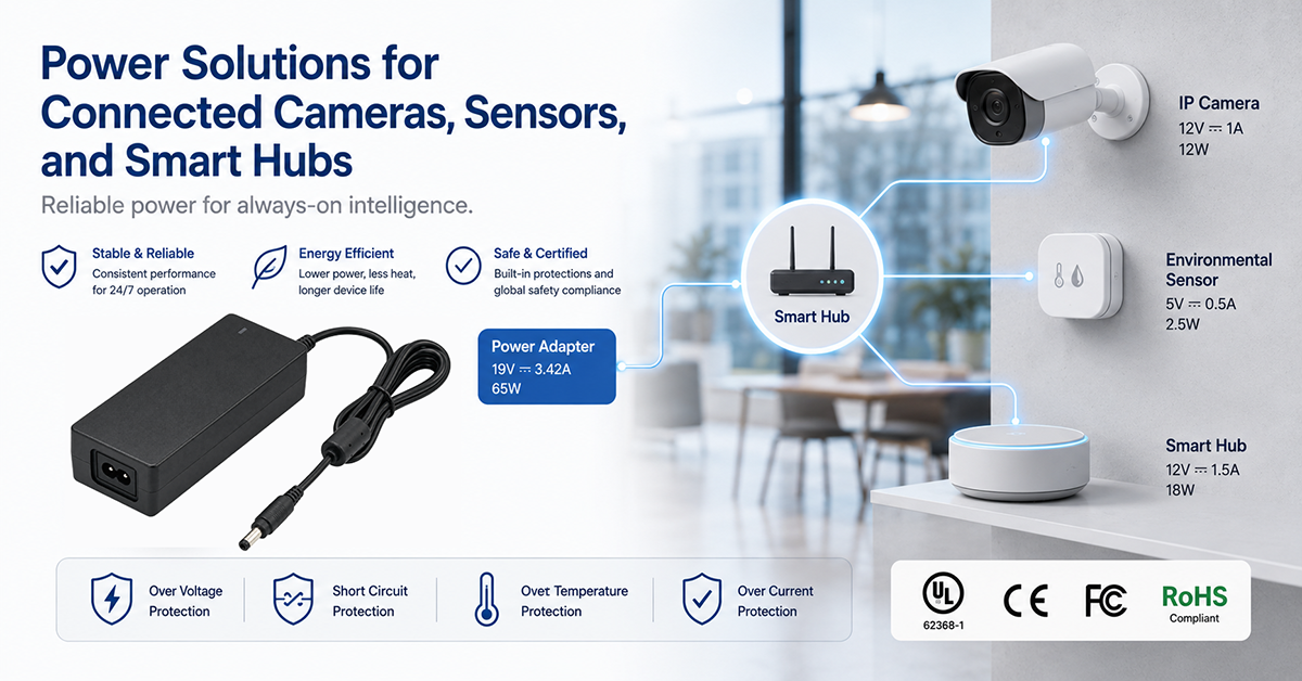
Connected cameras, sensors, and smart hubs form the backbone of a smart home ecosystem, and each device type has distinct power supply requirements. Outdoor security cameras must operate reliably in extreme temperatures and weather conditions while maintaining continuous video recording. Battery-powered sensors must minimize power consumption to maximize battery life between charges. Smart hubs must provide consistent power to maintain network connectivity and process data from dozens of connected devices.
This guide covers power supply considerations for connected cameras, sensors, and smart hubs: PoE and adapter power options, outdoor camera power requirements, battery-powered sensor design, hub power architecture, and OEM design guidance.
Power Options for Connected Cameras
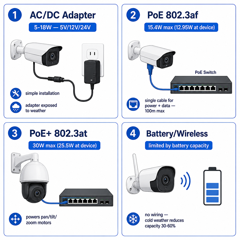
Connected cameras can be powered through AC/DC adapters, Power over Ethernet (PoE), or battery (wireless cameras). The choice depends on the installation environment, power requirements, and data connectivity.
Power Source Comparison
| Power Source | Typical Power Available | Pros | Cons |
|---|---|---|---|
| AC/DC adapter (wall plug or desktop) | 5–18W (5V, 12V, 24V) | Simple installation, no data cabling needed, wide compatibility | Requires AC outlet near camera; adapter exposed to weather (outdoor) |
| PoE (IEEE 802.3af) | 15.4W max (12.95W at device) | Single cable for power and data; standardized; UPS-backed | Requires PoE switch or injector; limited to 100m cable |
| PoE+ (IEEE 802.3at) | 30W max (25.5W at device) | More power for pan/tilt/zoom cameras | Higher switch cost |
| PoE++ (IEEE 802.3bt) | 60–100W max | High-power cameras with heating, IR illumination | Specialized switch required |
| Battery (wireless) | Limited by battery capacity | No wiring needed; flexible placement | Limited recording time; frequent charging; cold-weather battery issues |
Outdoor Camera Power Challenges
| Challenge | Effect | Mitigation |
|---|---|---|
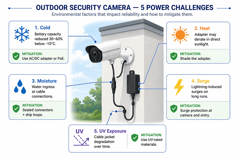
| Cold temperature | Battery capacity reduced by 30–60% below −10°C | Use AC/DC adapter or PoE in cold climates; select low-temperature batteries |
| Heat | Adapter may derate or fail in direct sunlight | Select adapter with appropriate temperature rating; shade the adapter |
| Moisture | Water ingress at cable connections | Sealed connectors; drip loops; IP-rated adapter enclosure |
| Surge | Lightning-induced surges on long cable runs | Surge protection at camera and building entry point |
| UV exposure | Cable jacket and housing degradation | UV-rated cable and housing materials |
Adapter Selection for Cameras
| Camera Type | Typical Adapter | Considerations |
|---|---|---|
| Indoor IP camera | 5V/2A or 12V/1A wall plug | Low power; simple installation |
| Outdoor bullet camera | 12V/2A or 24V/1A desktop | Surge protection; cold-start capability |
| PTZ (pan/tilt/zoom) camera | 24V/2.5A or PoE+ | Higher power for motors and heater |
| Doorbell camera | 12–24VAC (existing doorbell wiring) or 12V/1A adapter | Compatibility with existing transformer; low standby for mechanical chime |
| PoE camera | PoE switch or injector | Verify camera’s PoE class (af/at/bt) |
Why This Matters
- Outdoor cameras powered by AC/DC adapters require the adapter to be installed in a weather-protected location or to be IP-rated. The adapter is often the weakest link in outdoor camera reliability.
- PoE cameras simplify installation by carrying power and data on one cable but are limited to 100m from the switch. For longer runs, an AC/DC adapter at the camera location is required.
- Battery-powered cameras in cold climates may need charging 2–3× more frequently in winter than in summer due to battery capacity reduction.
What OEMs Should Do Now
- For outdoor cameras, specify adapters with cold-start capability to −20°C or lower and surge protection per IEC 61000-4-5 Level 3.
- Design cameras to accept both AC/DC adapter and PoE power with automatic detection and switching.
- For battery-powered cameras, specify the operating temperature range and expected battery life at the minimum temperature to set user expectations.
Smart Sensor Node Power Design
Sensor Power Budget Example
| Sensor Component | Active Power | Sleep Power | Duty Cycle | Average Power |
|---|---|---|---|---|
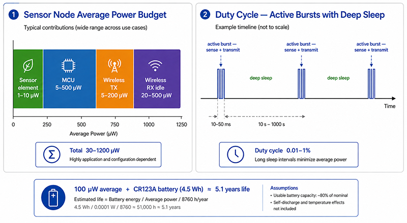
| Sensor element (PIR, thermistor) | 10–100µW | 0.1–1µW | 0.1–1% | 1–10µW |
| MCU (active) | 5–50mW | 0.1–10µW | 0.1–1% | 5–500µW |
| Wireless TX (Zigbee/Z-Wave) | 50–200mW | 0.1–1µW | 0.01–0.1% | 5–200µW |
| Wireless RX (idle listening) | 20–50mW | — | 0.1–1% | 20–500µW |
| Total sensor node | 30–1200µW |
Battery Life Calculation (illustrative)
- Estimated life: 4.5Wh / 0.0001W = 45,000 hours ≈ 5.1 years
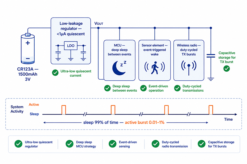
Power Architecture for Battery Sensors
| Strategy | Description | Typical Saving |
|---|---|---|
| Deep sleep between reports | MCU in lowest power state; wake on timer or event | 90–99% reduction from active power |
| Duty-cycled wireless | Transmit data in short bursts; sleep between | Reduces average TX power by 100–1000× |
| Event-triggered wake | Sensor interrupt wakes MCU instead of periodic polling | Eliminates polling power |
| Low-leakage power supply | Select regulator with <1µA quiescent current | Adds 1–5µW vs 10–50µW for standard regulator |
| Capacitive storage for TX burst | Capacitor stores energy for wireless transmission | Allows higher TX power without battery voltage drop |
AC-Powered Sensor Nodes
Some sensor nodes (particularly those with continuous monitoring requirements, such as smoke detectors and leak sensors) are AC-powered with battery backup. These use an external AC/DC adapter or direct AC input with a small internal power supply.
Why This Matters
- Battery life is the most important user-facing specification for wireless sensors. A sensor that requires battery changes every 6 months has poor user acceptance compared to one that lasts 3–5 years.
- The wireless transmission is typically the largest power consumer. Minimizing transmission frequency and duration has the greatest impact on battery life.
- Self-discharge of the battery itself (2–5% per year for lithium primary cells) becomes significant for sensors designed to last 5–10 years.
What OEMs Should Do Now
- Calculate the sensor node’s average power consumption including all operating modes (active, sleep, wireless TX/RX) weighted by duty cycle.
- Select a regulator with quiescent current below 1µA to minimize power waste during sleep.
- Test battery life under real operating conditions, not just calculated from datasheet values. Account for battery self-discharge, temperature effects, and manufacturing tolerances.
Smart Hub Power Architecture
Hub Power Requirements
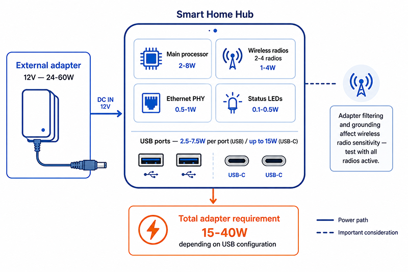
| Subsystem | Typical Power | Notes |
|---|---|---|
| Main processor (application processor) | 2–8W | Varies with processing load and features |
| Wireless radios (2–4 radios) | 1–4W | Zigbee + Wi-Fi + BT + Thread |
| Ethernet PHY + magnetics | 0.5–1W | Always active for network connectivity |
| USB host ports (if applicable) | 2.5–12W (5V at 0.5–2.4A per port) | Power for connected USB devices |
| Status indicators | 0.1–0.5W | LEDs |
| Total hub power | 5–25W | Depends on features and USB ports |
Hub Power Architecture
- Hub internal circuits: 5–12W typical
- USB ports: 2.5–7.5W per port (standard USB) or up to 15W per port (USB-C)
- Total adapter requirement: 15–40W depending on USB port configuration
Adapter Form Factor
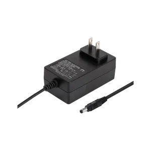
Smart hubs typically use a desktop adapter (12–24W for basic hubs, 24–60W for hubs with multiple USB ports). The adapter should be rated for continuous operation.
Why This Matters
- A smart hub’s USB ports are often used to power connected sensors, camera receivers, or battery chargers. The total USB power budget must be included in the adapter selection.
- The hub’s wireless radios can introduce RF noise that couples back into the power supply. The adapter’s filtering and grounding affect wireless performance.
- A hub with insufficient adapter capacity may drop USB devices or reboot when all radios are active and USB ports are loaded simultaneously.
What OEMs Should Do Now
- Calculate the hub’s total power requirement including all internal circuits and the maximum load on all USB ports simultaneously.
- Select an adapter rated for at least 120% of the calculated maximum power for continuous operation.
- Verify that the adapter’s output filtering does not introduce noise that degrades wireless radio sensitivity. Test with all radios active and USB ports loaded.
Q: Can I use a PoE injector to power an outdoor security camera if there’s no AC outlet nearby?
A: Yes, PoE is specifically designed for this scenario. The PoE injector is installed at the building’s AC outlet, and the camera is powered through the Ethernet cable. The maximum cable length is 100m. Verify the camera’s PoE class (802.3af: 12.95W, 802.3at: 25.5W) to ensure the injector provides adequate power.
Q: How long do smart sensor batteries typically last?
A: Battery life depends on the sensor type, reporting frequency, wireless protocol, and environmental temperature. Typical ranges: motion sensors (3–5 years), door/window sensors (3–7 years), temperature/humidity sensors (2–5 years), leak sensors (3–5 years). Always verify with the manufacturer’s specified battery life under typical use conditions.
Q: What adapter voltage is typical for a smart home hub with USB ports?
A: 12V is the most common adapter voltage for smart home hubs. A 12V/2–3A adapter (24–36W) provides adequate power for the hub’s internal circuits plus one or two USB ports. Hubs with multiple high-power USB ports may require 12V/5A (60W) or a 24V adapter.
Conclusion
Connected cameras, sensors, and smart hubs each have distinct power supply requirements. Outdoor cameras need adapters with cold-start capability, surge protection, and weather-resistant installation. Battery-powered sensors require ultra-low-power design with deep sleep and event-triggered wake to achieve multi-year battery life. Smart hubs must be sized to power both their internal circuits and connected USB devices. In each case, selecting the right power source—AC/DC adapter, PoE, or battery—depends on the device’s installation environment, power requirements, and usage pattern.
Related Resources
🔌 Related Products
🏭 Related Applications
📖 Related Guides
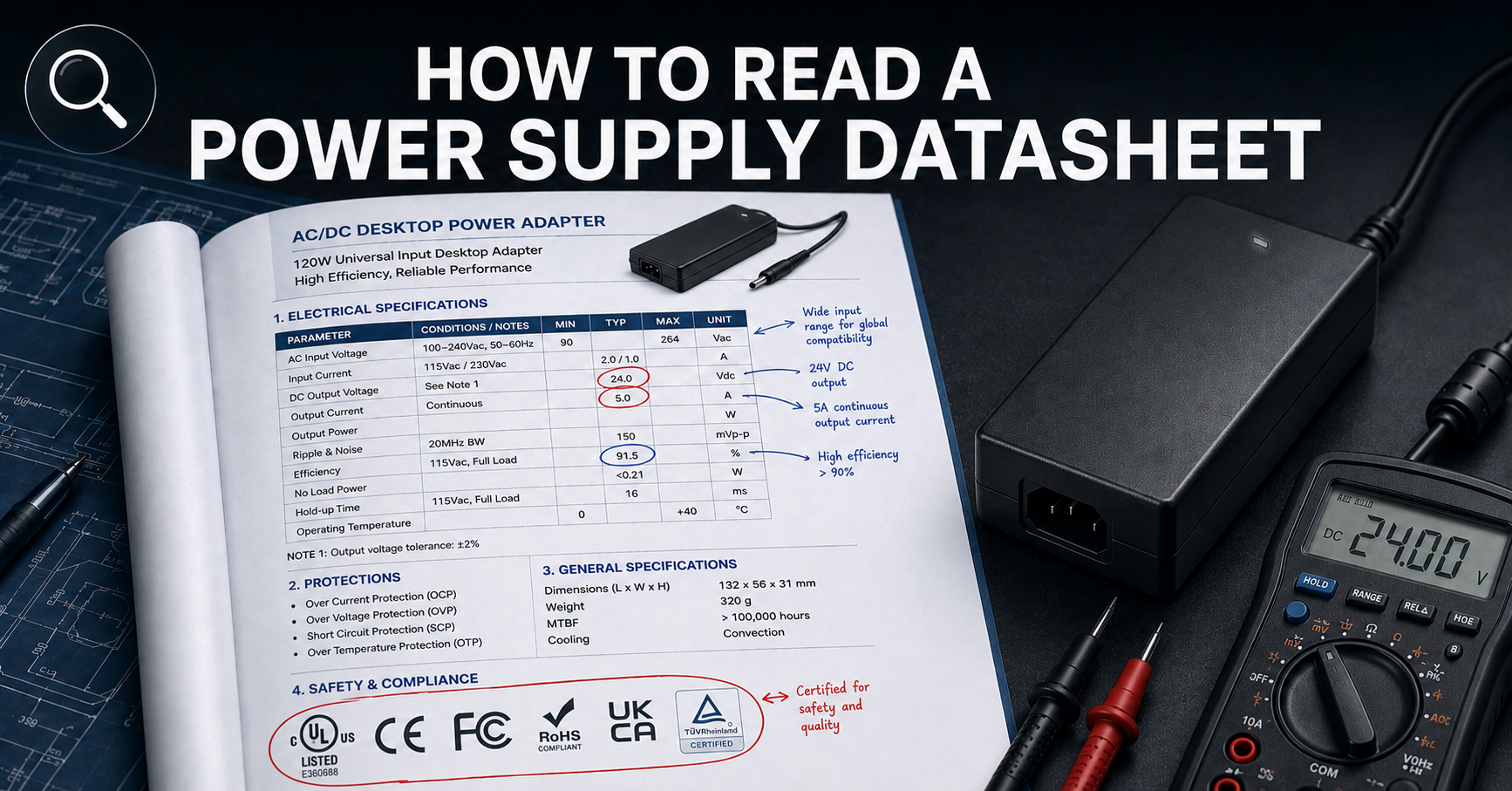
How to Read a Power Supply Datasheet
Learn how to evaluate connector specifications in a datasheet — current ratings, derating curves, certification verification.
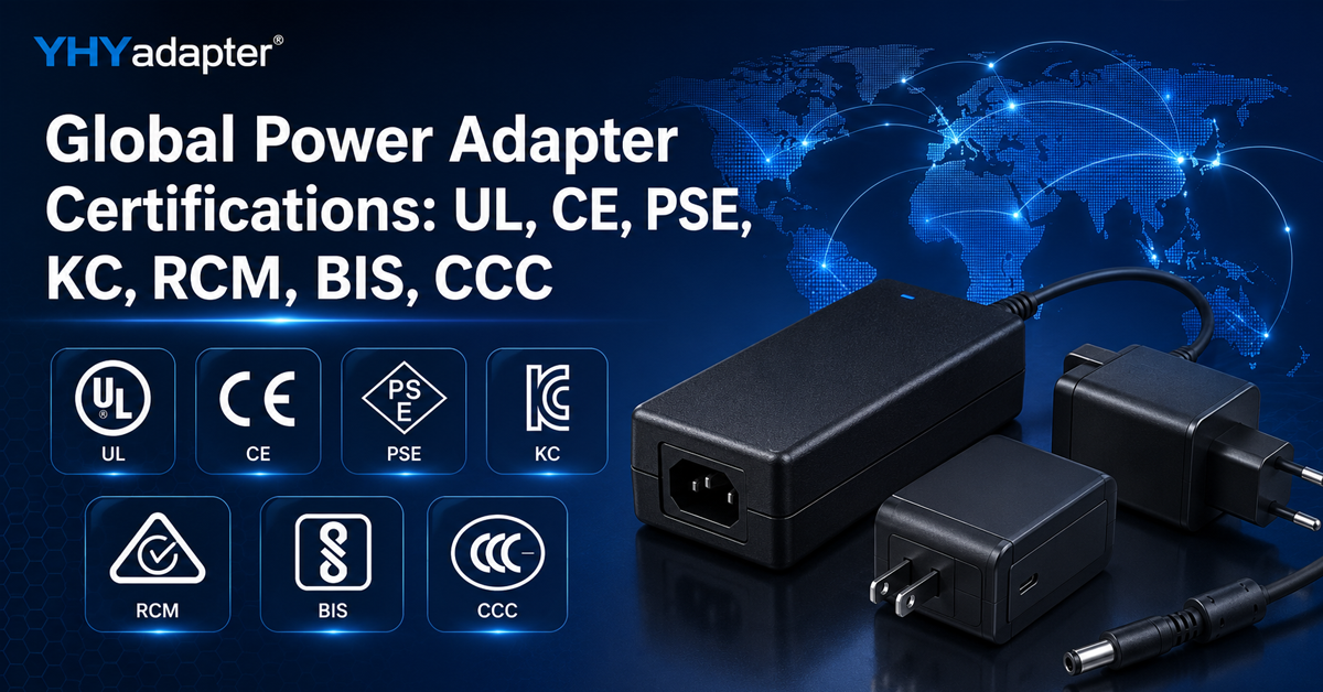
✅ Related Certifications
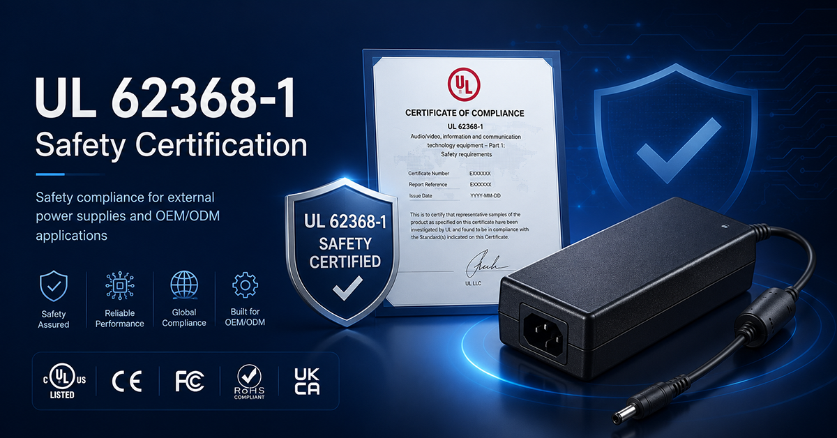
UL 62368-1 Safety Certification
Safety standard covering connector creepage/clearance, temperature rise, and strain relief requirements for IT/AV equipment power adapters.