
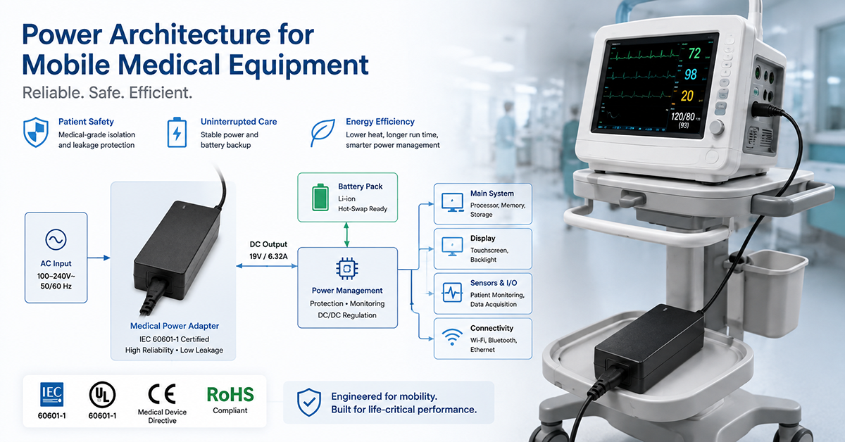
Healthcare mobility is transforming medical device design. Equipment that was once stationary — patient monitors, ultrasound systems, diagnostic workstations — is now expected to operate on carts, move between rooms, and function during patient transport. This shift places new demands on power architecture: battery-backed operation, medical-grade isolation in mobile contexts, thermal management in compact enclosures, and power distribution across interconnected subsystems.
This guide covers the complete power architecture for mobile medical equipment: from AC mains input to individual device loads, with specific guidance for medical carts, portable ultrasound, patient monitors, infusion pumps, portable diagnostics, and docking stations.
For foundational medical power knowledge and selection frameworks — leakage current, isolation design (2MOPP/2MOOP), and adapter selection — see the Medical Device Power Adapters hub.
Medical Cart Power Architecture
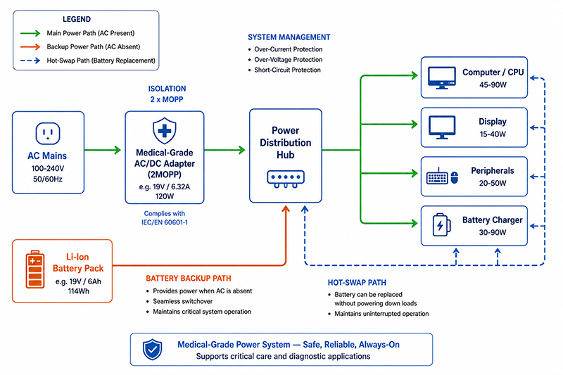
The medical cart is the most common mobile medical platform, integrating a computer, display, peripherals, and battery backup into a single mobile unit.
Central Power Distribution Design
A medical cart’s power architecture follows a centralized topology:
AC Mains → Medical-Grade AC/DC Adapter → Battery Charger → DC Distribution → Device Loads
| Component | Typical Power | Voltage | Notes |
|---|---|---|---|
| Computer / CPU | 45–90W | 19V / 12V | Laptop-grade or embedded PC |
| Medical-grade display (15–22″) | 15–40W | 12V / 24V | Touchscreen, high brightness |
| Wireless / RFID module | 2–5W | 5V / 3.3V | Communication, location tracking |
| Peripherals (scanner, printer) | 20–50W | 12V / 24V | Intermittent use |
| Battery charger (internal) | 30–90W | Per battery chemistry | Simultaneous charging + device power |
| Total System | 110–275W | Typically 180W–240W nominal |
Architecture decisions:
- Single vs multi-rail power supply: A single-output adapter (e.g., 24V/10A = 240W) with downstream DC-DC converters for each voltage rail is simpler and more efficient than multiple AC-DC adapters.
- Power distribution hub: A central PCB or wiring harness distributes power from the adapter/charger to each subsystem. Each branch should have individual overcurrent protection (eFuse or PTC).
- Grounding strategy: Single-point ground at the adapter output to prevent ground loops between the computer, display, and medical peripherals.
Battery-Backed Operation
Hot-swappable battery design: The cart must continue operating when the battery is removed and replaced. This requires a power path management system that seamlessly switches between AC adapter and battery without interrupting the output.
Runtime requirements:
- Standard clinical cart: 2–4 hours continuous operation
- Critical care / emergency transport: 8+ hours
- Battery chemistry: Li-Ion (LiFePO₄ for longer cycle life in high-use carts)
Battery management:
- State of charge (SoC) monitoring: Coulomb counting + voltage-based correction
- State of health (SoH) tracking: Cycle count, capacity fade estimation
- Automatic conditioning: Periodic full discharge/charge cycles if the cart is rarely unplugged
Portable Ultrasound
Portable ultrasound systems range from handheld devices (15W) to cart-based systems (60W+). Their power architecture must balance image quality — which demands low noise — with portability.
Power Budget Analysis
| Subsystem | Handheld Unit | Cart-Based Portable |
|---|---|---|
| Beamformer / probe electronics | 5–10W | 10–20W |
| Display | 2–5W (small LCD) | 8–15W (15″ LCD) |
| Processing / GPU | 3–8W | 5–20W |
| Battery charging | 5–10W | 10–30W |
| Total | 15–33W | 35–85W |
Critical Design Requirements
Low noise output: Ultrasound image quality depends on signal-to-noise ratio (SNR). Power supply ripple and noise must be exceptionally low — typically <10mVpp for the probe power rail. Switching power supplies require post-regulation (LDO) for probe analog circuits.
Isolation: The probe is patient-connected, so the probe power rail must be isolated from the AC mains with 2MOPP (4000VAC reinforced isolation). A medical-grade AC/DC adapter with 2MOPP isolation is the most straightforward approach.
Battery charging during use: The power adapter must supply both the operating current and the charging current simultaneously. If the system draws 50W and the battery charges at 30W, the adapter must be rated for at least 80W continuous.
Patient Monitor
Patient monitors operate continuously — 24 hours a day, 7 days a week — making power reliability the primary design concern.
Continuous Operation Requirements
- MTBF target: >100,000 hours for the power subsystem
- Power redundancy: The monitor must tolerate failure of its primary power source
- Zero-switchover: Transition between AC adapter and internal battery must be seamless — no voltage dropout visible to the electronics
Power Redundancy Architecture
Dual power input design:
AC Adapter ──────┐
                 ├── OR-ing circuit ──→ System Power
Internal Battery ──┘
The OR-ing circuit (using Schottky diodes or ideal diode OR-ing controllers) automatically selects the higher voltage source. When AC power is present, the adapter voltage (slightly higher than battery voltage) powers the system and charges the battery. When AC power drops, the battery seamlessly takes over.
Hot-swap adapter replacement: The monitor should continue operating if the AC adapter is removed and replaced. The battery provides power during the swap window. This requires at least 30 seconds of battery runtime with a fully charged battery before low-battery warning.
Connector Reliability
Patient monitors are frequently plugged and unplugged during room transfers. Key connector requirements:
- Locking DC connectors: Threaded locking collars prevent accidental disconnection during movement
- Keyed connectors: Different voltage rails (12V, 24V) must use different keying to prevent misconnection
- Strain relief: Both adapter-side and device-side strain relief to prevent cable damage from repeated flexing
- Minimum 5,000 mating cycles: Clinical environments require robust connector life
Infusion Pump
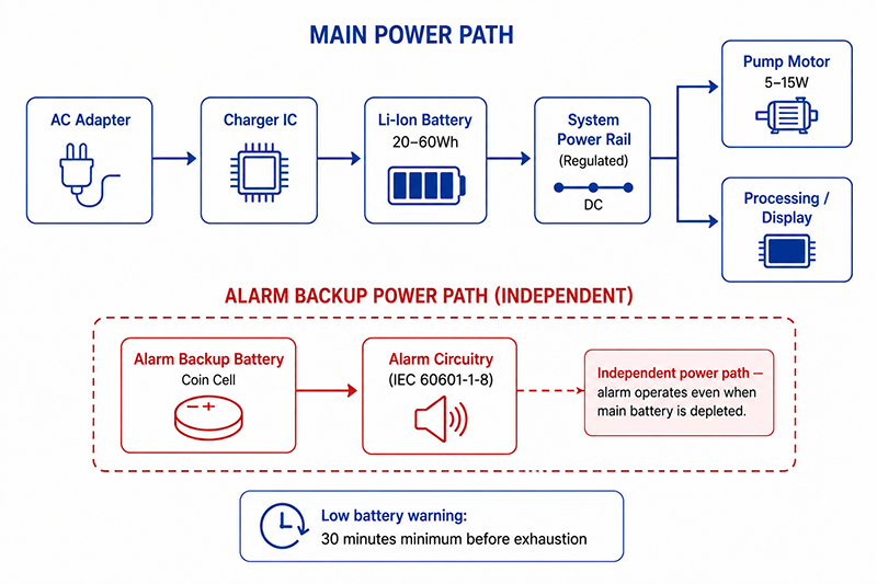
Infusion pumps are among the most power-sensitive medical devices — they must operate reliably at very low power levels and maintain alarm integrity regardless of battery state.
Low-Power Operation
| Operating State | Power Consumption | Duration |
|---|---|---|
| Active infusion | 5–15W | Per therapy duration |
| Standby (paused) | 2–5W | Between infusions |
| Sleep (deep standby) | <1W | Extended storage |
Stepper motor efficiency: Microstepping reduces power consumption but increases controller complexity. Full-step driving is more efficient for continuous infusion at moderate rates. For very low flow rates (<1 mL/hr), microstepping is necessary for smooth operation.
Battery Backup Sizing
- Minimum runtime: 4 hours (typical hospital guideline)
- Extended runtime: 8+ hours (transport ICU, home care)
- Battery capacity range: 20–60Wh depending on the pump class
- Battery type: Li-Ion for energy density (smaller device) or NiMH for lower cost
Alarm Power Integrity
Alarm circuits require independent power path design:
- Dedicated alarm power rail: The alarm system must have its own power path from the battery, separate from the pump motor
- Backup alarm battery: An independent small battery (coin cell or small Li-Ion cell) dedicated to alarm electronics ensures alarm sounds even when the main battery is fully depleted
- Low battery warning: IEC 60601-1-8 requires at least 30 minutes advance warning before battery exhaustion. The alarm must activate with sufficient lead time for clinical intervention.
Portable Diagnostic Equipment
Defibrillators / AEDs
Defibrillators present a unique power challenge: they must charge a high-voltage capacitor bank (100–200J) in under 10 seconds.
Peak power during capacitor charging:
- Energy required: 200J
- Charge time: 10 seconds
- Average charging power: 20W
- Peak power (first few seconds, capacitor at low voltage): 10kW+ instantaneous
This peak is supplied by the battery, not the AC adapter. The battery must have a high discharge rate capability (Li-Ion with low internal resistance or LiFePO₄).
AC adapter requirement: Must support simultaneous charging of the battery and limited capacitor charging at reduced rate. A 60–90W medical-grade adapter is typical.
ECG / Holter Monitors
- Power consumption: 0.5–3W continuous, extremely low
- Noise requirement: <10µVpp for ECG signal integrity — the lowest noise requirement of any medical device category
- Battery life target: 24–72 hours continuous recording
- AC adapter: Optional for extended monitoring. When used, must have exceptionally low output noise. Linear regulators on ECG analog circuits are often necessary despite their efficiency penalty.
Pulse Oximeters (Portable)
- Power consumption: 0.3–2W (battery-operated or USB-powered)
- Battery: AA/AAA alkaline or small Li-Ion pack
- AC adapter: Optional for bedside use. Low priority — most devices are primarily battery-operated.
Docking Stations
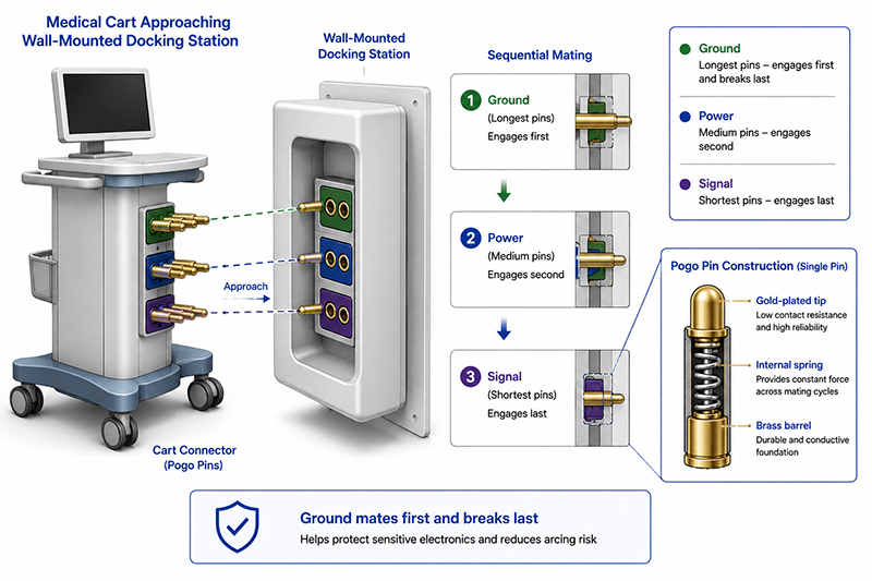
Docking stations provide the interface between mobile medical equipment and the hospital’s fixed infrastructure — AC power, data, and sometimes gas connections.
Contact Reliability
Docking contacts face repeated mating cycles and must maintain low resistance:
| Contact Type | Contact Resistance | Mating Cycles | Maintenance |
|---|---|---|---|
| Pogo pin (gold-plated) | <20mΩ | 10,000–50,000 | Clean every 6 months |
| Spring contact | <30mΩ | 5,000–20,000 | Replace at 50% of rated cycles |
| Magnetic connector | <50mΩ | 100,000+ | No mechanical wear, cleaning only |
| Blade / fork | <10mΩ | 10,000+ | Visual inspection only |
Self-cleaning contacts: Pogo pins with wiping action (slight lateral movement during mating) clear oxide buildup automatically. This is preferred for clinical environments where contact cleaning is inconsistent.
Misalignment tolerance: Docking station mechanical guides should provide ±2–3mm of alignment tolerance before the connector engages. Connectors should have float (spring-loaded mounting) to absorb the remaining misalignment.
Power Delivery Through Docking
| Power Level | Contact Count | Typical Applications |
|---|---|---|
| 15–60W | 4 pins (2 power + 2 ground) | Portable diagnostics, small carts |
| 60–150W | 6 pins (4 power + 2 ground) | Full medical carts with battery charging |
| 150–300W | 8+ pins | Large carts with integrated systems |
Sequencing requirements: Ground pins must mate first and break last. This requires physically longer ground pins (sequential pin design). Power pins are in the middle. Signal/data pins mate last.
Short-circuit protection: Each power pin should have individual current limiting. An eFuse per pin protects against contact debris shorting adjacent pins.
Battery Charging
Charger Selection for Medical Applications
Medical battery chargers must maintain 2MOPP isolation between the AC mains and the battery — the battery is a patient-accessible part in many configurations.
Charging profile (Li-Ion):
- Stage 1: Constant Current (CC) — typically 0.2C to 1C depending on battery capacity and required charge time
- Stage 2: Constant Voltage (CV) — 4.2V per cell (±1% precision), current tapers to termination threshold (~0.05C)
- Stage 3: Charge termination — stops charging to prevent overcharging
- Stage 4: Trickle / top-off — resumes charging when voltage drops below 4.05V per cell (optional)
Temperature-compensated charging:
- Li-Ion must not charge below 0°C or above 45°C
- Battery thermistor (NTC, typically 10kΩ at 25°C) monitored during charging
- Charge current derated above 40°C, terminated at 45°C
Safety During Charging
| Protection | Method | Trip Threshold |
|---|---|---|
| Overcharge | Precision voltage regulation (±0.5%) | 4.2V ±0.02V per cell |
| Overcurrent | Series current sense + limit | 1.1× programmed charge current |
| Overtemperature | NTC thermistor monitoring | 45°C at battery surface |
| Short circuit | Output disconnect (eFuse) | Instant on short |
| Reverse polarity | MOSFET reverse blocking | Continuous |
Charging While Operating (Power Path Management)
The device must operate simultaneously with charging. Two approaches:
- Linear power path: The system runs from the adapter. The charger IC independently charges the battery. Requires a power adapter rated for system power + charge power.
- TurboBoost / InstantBoost: The adapter supplies the system. If the system demand exceeds adapter capacity, the battery supplements the difference. Useful when a smaller, lighter adapter is preferred.
Autonomous charging: The battery pack should be removable and chargeable in an external charger while the device continues to operate on AC power. This allows continuous clinical use without downtime for charging.
Power Distribution
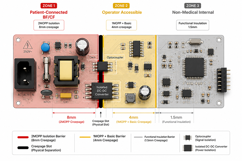
Isolation Zones
Per IEC 60601-1, medical equipment with patient-connected parts requires defined isolation zones:
| Zone | Isolation Requirement | Creepage | Typical Circuits |
|---|---|---|---|
| Patient-connected (BF/CF) | 2MOPP to mains | 8mm (250V) | Probe circuits, ECG leads, sensors |
| Operator-accessible | 1MOPP + basic | 4mm (250V) | Enclosure, controls, display |
| Non-medical (internal) | Functional only | 1.5mm | Logic circuits, wireless modules |
Physical implementation:
- Patient-connected circuits on a separate PCB section with physical slots or grooves between zones
- Optocouplers or isolated DC-DC converters crossing the isolation barrier
- Reinforced insulation (≥2mm) in transformer and optocoupler components
Power Sequencing
Proper power-up sequencing prevents latch-up and logic errors:
- Main power rail (12V/24V) — from adapter or battery
- CPU / core logic — enabled by power-good from main rail
- Peripherals — USB, display backlight, wireless modules
- Patient-connected circuits — last to power up, after CPU confirms safe state
Shutdown sequence: Reverse order. Patient-connected circuits power down first, then peripherals, then CPU performs safe shutdown (save state, close files), then main power disconnects.
Load Shedding
On battery power with limited remaining capacity, the system should shed non-critical loads:
| Priority | Loads | Action |
|---|---|---|
| 1 (Critical) | Monitoring circuits, alarms, CPU | Full power maintained |
| 2 (Important) | Display, storage, wireless | Reduced power (dim display, disable wireless) |
| 3 (Optional) | Peripherals, printer, secondary display | Disconnected |
Power Management
Energy Efficiency
Modern medical power adapters should meet or exceed:
| Metric | Target | Standard Reference |
|---|---|---|
| Full-load efficiency | ≥88% (60W), ≥89% (120W), ≥90% (180W+) | CoC Tier 2 |
| Average efficiency (25–100% load) | ≥87% | ENERGY STAR EPS 2.0 |
| No-load power | <0.1W | CoC Tier 2 |
Thermal Management in Compact Enclosures
Mobile medical equipment enclosures are compact and often fanless for noise and hygiene reasons.
External adapter advantage: An external AC/DC adapter removes the primary heat source from the device enclosure. The device only dissipates internal conversion losses (DC-DC converters, battery charging) — typically 5–15W vs 40–80W for an internal adapter.
Conduction cooling for internal adapters (if used):
- Thermal pads between adapter baseplate and device chassis
- Heat pipes for hot spots
- Aluminum chassis as heatsink
- No fan required for up to ~100W internal dissipation with proper design
Battery Health Management
| Practice | Frequency | Benefit |
|---|---|---|
| Full discharge/recharge cycle | Every 30–90 days | Calibrates SoC gauge |
| Store at 40–60% charge | Long-term storage | Maximizes calendar life |
| Avoid deep discharge (<10%) | Continuous | Prevents cell damage |
| Monitor internal resistance | Quarterly | Detects cell degradation early |
Replacement trigger: Replace battery pack when capacity falls below 60% of rated — or sooner if the device cannot complete a typical clinical shift on a full charge.
Recommended YHYadapter Products
| Model | Power | Medical Certification | Best Application |
|---|---|---|---|
| YHY-12005000 | 60W (12V/5A) | IEC/EN 60601-1 certified — YHY-080~560 series, ≤65W, Class II | Infusion pumps, portable diagnostics, pulse oximeters |
| YHY-24002500 | 60W (24V/2.5A) | IEC/EN 60601-1 certified — YHY-080~560 series, ≤65W, Class II | Patient monitors, 24V bus systems, small carts |
| Available by model | 120W+ | Confirm certification coverage with engineering team | Medical carts (monitor + computer + peripherals + charging) |
| Custom medical adapter | Per spec | Certification evaluated per project | OEM requirements (custom power, connector, mechanical) |
Selection by Equipment Type
| Equipment Type | Recommended Power Level | Key Requirements |
|---|---|---|
| Medical cart (full system) | 180–240W | 2MOPP, multiple output voltages, battery charging support |
| Patient monitor | 60–120W | Continuous operation, low noise, redundant input capable |
| Portable ultrasound | 60–120W | Very low noise (<10mVpp), 2MOPP |
| Infusion pump | 30–60W | Low power, IEC 60601-1-8 alarm compliance |
| Docking station | 60–180W | Contact reliability, hot-plug safe |
| Portable diagnostic | 30–60W | Compact, lightweight, medical-grade isolation |
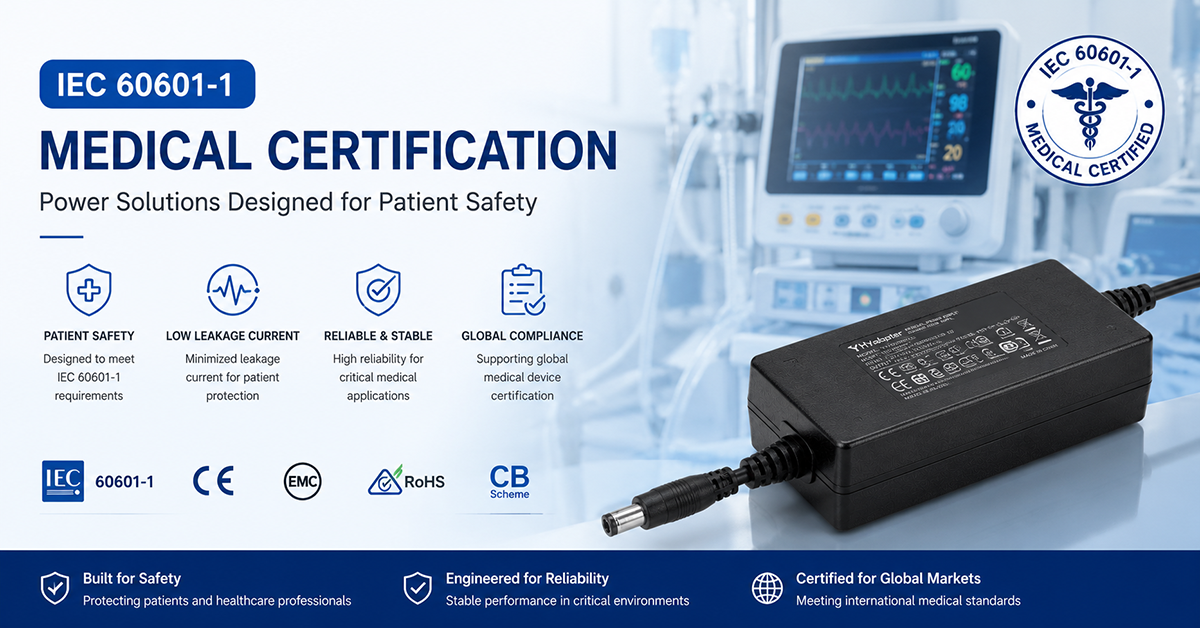
YHYadapter medical-grade adapter models — such as YHY-12005000 (12V/5A) and YHY-24002500 (24V/2.5A) — feature 2MOPP reinforced isolation, low leakage current, and carry IEC/EN 60601-1 certification as part of the YHY-080~560 series (≤65W, Class II). Certification for other models is available by model. OEM customization options include custom output voltage, connector type, cable length, and mechanical packaging
Related Resources
🔌 Related Products
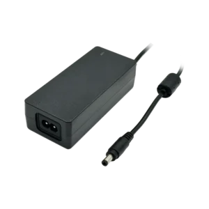
12V 65W Desktop Adapter
60W-class desktop platform, low-leakage design — reference for medical-related equipment
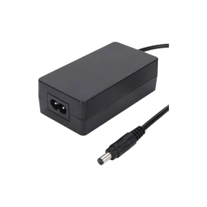
12V 5A 60W Medical Desktop Adapter (YHY-12005000)
IEC/EN 60601-1 confirmed medical model
🏭 Related Applications
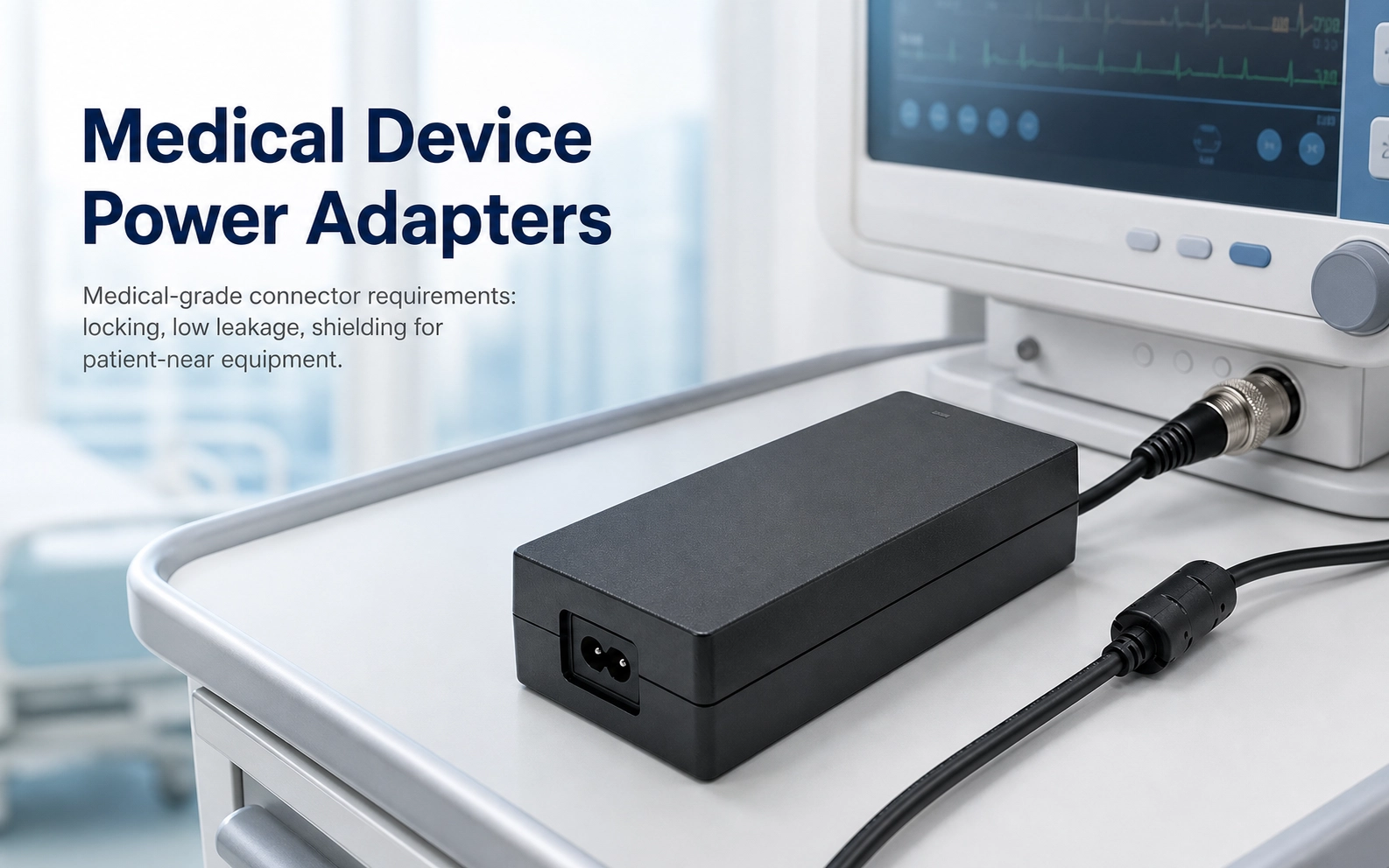
Medical Device Power Adapters
Medical device power solutions and IEC 60601-1 compliance reference
📖 Related Guides
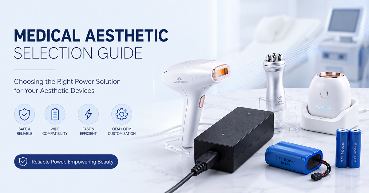
Medical Aesthetic Selection Guide
Power adapter selection for medical aesthetic devices
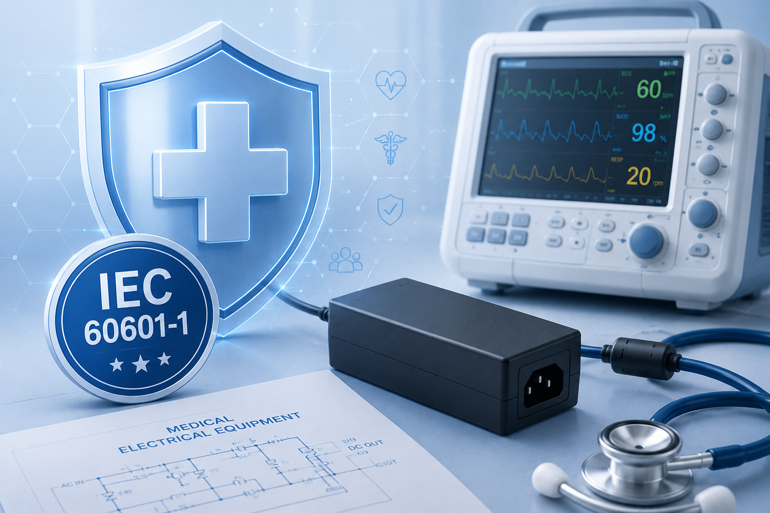
IEC 60601-1 Medical Cert Guide
IEC 60601-1 certification guide for medical/beauty power supplies
IPL Hair Removal Power Supply Guide
Power supply engineering guide for IPL hair removal devices
✅ Related Certifications
IEC 60601-1
Medical electrical equipment safety standard — compliance reference for medical/beauty devices