
The 24V DC bus is the lifeblood of industrial automation. From PLC racks and HMI panels to sensor networks and actuator controllers, the 24V supply dictates whether a production line runs or stops. A power supply failure at this level isn’t just a component replacement — it’s production downtime, missed deadlines, and direct revenue loss.
This guide covers the practical engineering decisions for selecting 24V power supplies in automation systems. It focuses on system architecture, load profiling, voltage drop management, and connectorization — the factors that separate a reliable installation from a problematic one.
For a general industrial adapter selection framework, start with the Industrial Power Adapter Selection Guide (IA01). For specific equipment guidance, see Power Supply for PLC Systems.
24V System Architectures
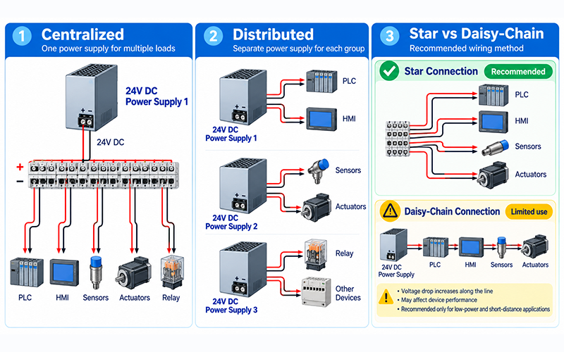
The architecture you choose for distributing 24V power determines system reliability, maintainability, and scalability. There are three primary approaches.
Centralized Power Distribution
A single 24V power supply feeds the entire control cabinet or system. All loads connect to a common DC bus through terminal blocks or distribution boards.
Best for: Small to medium control cabinets (<10A total load), single-machine systems.
Advantages:
- Lowest component cost — one power supply
- Simple wiring and troubleshooting
- Single point of voltage monitoring
Limitations:
- Single point of failure affects entire system
- Voltage drop over long cable runs within cabinet
- Difficult to expand beyond initial capacity
Distributed Power Architecture
Multiple 24V power supplies are placed closer to their respective load groups. Each supply serves a zone or subsystem.
Best for: Large systems (>15A total), multi-panel installations, machines with physical separation between subsystems.
Advantages:
- Reduced voltage drop — supplies close to loads
- Zone isolation — a fault in one zone doesn’t affect others
- Easier expansion — add zones without upgrading central supply
- Redundancy possible — N+1 configuration for critical zones
Limitations:
- Higher component cost
- More complex wiring and coordination
- Ground loop potential between zones
Daisy-Chain vs Star Configuration
Star configuration: Each load or sub-panel receives a dedicated cable from the central distribution point. Preferred for critical systems because a single branch fault doesn’t affect others.
Daisy-chain: Loads are connected sequentially along a single cable run. Lower wiring cost, but a fault at any point can interrupt downstream loads. Only suitable for non-critical, low-power devices with short cable runs.
Recommendation: Use star configuration for control systems and safety-related loads. Reserve daisy-chain for non-critical sensors with well-defined power budgets.
Load Profiles and Power Budgeting
Understanding the complete 24V load is the foundation of power supply selection. The total current draw is often 2–3× higher than initial estimates because field devices are frequently omitted from the budget.
Typical 24V Load Composition
| Component | Current (per unit) | Notes |
| PLC CPU module | 0.3–0.8 A | Depends on processor speed and integrated I/O |
| Digital input module (16ch) | 0.05–0.15 A | Sinking vs sourcing type |
| Digital output module (16ch) | 0.1–0.5 A + load current | Load current must be itemized per channel |
| Analog I/O module | 0.1–0.3 A | Per module, independent of signal level |
| HMI panel (7–10″) | 0.5–1.2 A | Backlight brightness dependent |
| Proximity sensor | 0.01–0.03 A | Inductive or capacitive type |
| Solenoid valve | 0.1–0.5 A | Activation peak, holding current ~40% lower |
| Small DC motor/actuator | 0.5–3.0 A | Depends on size and mechanical load |
Practical Power Budget Example
Consider a small-to-medium automation cell:
| Component | Qty | Unit Current | Total Current |
| PLC CPU | 1 | 0.8A | 0.8A |
| Digital input modules | 4 | 0.1A | 0.4A |
| Digital output modules | 3 | 0.65A (incl. load) | 2.0A |
| HMI panel | 1 | 0.8A | 0.8A |
| Proximity sensors | 20 | 0.02A | 0.4A |
| Solenoid valves | 8 | 0.3A (peak) | 2.4A |
| Continuous total | 6.8A |
With 30% margin: 6.8A × 1.3 = 8.84A → approximately 215W at 24V.
Selection: A 240W / 10A 24V power supply provides adequate headroom for future expansion and handles transient loads from simultaneous solenoid activation.
Key Budgeting Rules
- Itemize every field device — sensors and actuators are the most commonly omitted items
- Separate continuous from peak — the supply must handle both: continuous rating for steady state, peak capability (120–150% for 1–5 seconds) for transients
- Add 30% minimum margin — industry standard for industrial automation avoids costly field retrofits
- Verify startup sequence — simultaneous power-up of all modules can produce 150–300% inrush for 10–100ms
24V Power Supply Selection Criteria
Power Rating
The primary specification. Calculate total continuous load, add margin, and select the next standard power rating.
Rule of thumb: P_supply = 1.3 × Σ(P_load). For 24V systems, standard ratings are 60W (2.5A), 120W (5A), 240W (10A), and 480W (20A).
Output Regulation
- Load regulation: <3% from no-load to full-load — ensures stable voltage for sensitive electronics
- Line regulation: <1% for ±10% input variation — maintains output during line fluctuations
- Ripple and noise: <100mVpp for general automation; <50mVpp for analog sensor systems
Efficiency
Higher efficiency reduces the heat that has to leave the cabinet. Specify efficiency at the load the supply actually operates at, and carry the resulting losses into the enclosure thermal calculation — those losses contribute to the cabinet’s internal temperature, which in turn affects capacitor and fan lifetime.
Form Factor
| Form Factor | Best Application |
| DIN rail mount | Control cabinet installation, standard industrial |
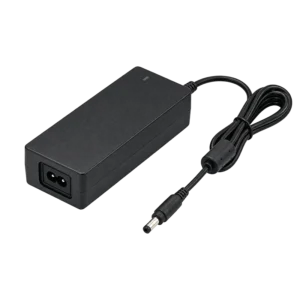
| Desktop adapter | Standalone equipment, test benches, small systems |
| Panel mount | Embedded in OEM equipment, custom enclosures |
| Open-frame | OEM integration requiring custom thermal management |
Protection Requirements
Every 24V industrial supply should include:
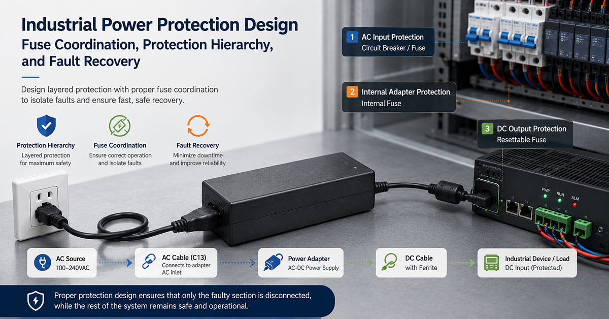
- Overcurrent protection — automatic current limiting or foldback
- Overvoltage protection — output clamps or crowbar to prevent load damage
- Short-circuit protection — hiccup mode for automatic recovery
- Thermal shutdown — prevents damage under overtemperature conditions
For detailed protection design methodology, see Industrial Power Protection Design.
Environmental Rating
- Operating temperature: -20°C to +70°C minimum for general industrial; wider range for harsh environments
- Ingress considerations: YHYadapter adapters are for indoor control-side use; where an installation needs protection against dust or water, that protection is provided at the equipment enclosure level by the equipment OEM
- Derating: Output power decreases at temperature extremes — verify derating curves
For harsh environment selection, see Choosing Power Adapters for Harsh Industrial Environments.
Certifications
| Standard | Relevance to 24V Automation |
| UL 508 | Industrial control equipment — required for US panel installations |
| UL 1310 Class 2 | Limited power source — simplifies wiring in many jurisdictions |
| IEC 62368-1 | International safety standard for industrial/commercial equipment |
| CE (LVD + EMC) | Required for EU market |
| FCC Part 15 | Required for US market (EMC) |
24V Cable and Wiring Considerations
Voltage Drop
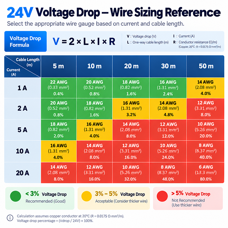
Voltage drop is the most common hidden issue in 24V installations. At 24V, a 5% drop (1.2V) can cause marginal operation or random resets in sensitive loads.
Voltage drop formula: V_drop = 2 × L × I × R_cable
Where: L = cable length in meters, I = current in amperes, R_cable = resistance per meter
Wire Sizing Table
| Current (A) | Cable Length | Min Wire Gauge |
| 1A | 20m | 0.75mm² (AWG 18) |
| 1A | 50m | 1.5mm² (AWG 16) |
| 2A | 20m | 1.0mm² (AWG 17) |
| 2A | 50m | 2.5mm² (AWG 14) |
| 5A | 20m | 2.5mm² (AWG 14) |
| 5A | 50m | 4.0mm² (AWG 12) |
| 10A | 20m | 4.0mm² (AWG 12) |
| 10A | 50m | 6.0mm² (AWG 10) |
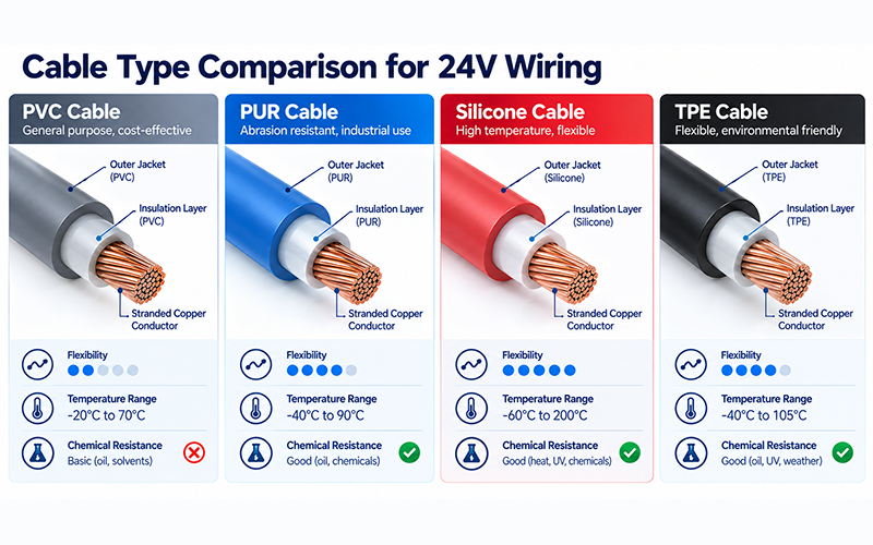
Practical rule: For 24V runs over 10 meters, calculate voltage drop before selecting cable gauge. A difference of one gauge size can mean the difference between reliable operation and intermittent faults.
Cable Type Selection
| Cable Type | Flexibility | Temperature Range | Chemical Resistance | Best Use |
| PVC | Moderate | -20°C to +70°C | Low | General cabinet wiring |
| PUR | High | -40°C to +90°C | High | Cable chains, moving parts |
| Silicone | Very high | -60°C to +180°C | Moderate | High-temperature areas |
| TPE | High | -40°C to +105°C | High | Flexible, oil-resistant |
Connectorization
- Terminal blocks: Screw or spring-cage — preferred for permanent cabinet wiring
- M12 power connectors: Sealed M12-style connectors, common for field I/O and distributed device power
- Wire ferrules: Required on stranded wire for terminal block connections — prevents strand breakage
- Ferrule sizing: Match ferrule gauge to wire gauge — undersized ferrules cause poor contact
For detailed connector selection guidance, see Industrial Power Connector Selection Guide.
Fusing per Branch
Each branch circuit drawing >3A should have individual overcurrent protection. Use terminal block fuses or circuit breakers at the distribution point.
Recommended YHYadapter Products
| Model | Power Output | Form Factor | Key Features |
| YHY-24002500 | 60W / 2.5A (24V) | Desktop, compact | UL 1310 Class 2, OCP/OVP/SCP |
| YHY-24005000 | 120W / 5A (24V) | Desktop | UL 1012, IEC 61558, OCP/OVP/SCP |
| 240W+ (available by model) | 240W+ / 10A+ | Desktop | Confirm certification and specifications with engineering |
| Custom OEM | Per spec | Per design | Custom voltage, connectors, temperature range, conformal coating |
Selection Matrix
| System Power Range | Recommended Product | Application |
| <60W (<2.5A) | YHY-24002500 | Sensor networks, small PLC with minimal I/O |
| 60–120W (2.5–5A) | YHY-24005000 | PLC + I/O + HMI + sensors |
| 120–240W (5–10A) | Available by model | Multi-device automation, future expansion |
| >240W | Multiple units or custom | Large systems, distributed architecture |
Selection Checklist
Use this checklist when specifying a 24V power supply for an automation system:
- [ ] Itemized load inventory (all devices, including field devices)
- [ ] Continuous + peak current calculated with ≥30% margin
- [ ] Startup inrush current assessed (simultaneous vs sequential power-up)
- [ ] Voltage drop calculated for cable runs >10 meters
- [ ] Form factor matches installation (DIN rail / desktop / panel)
- [ ] Environmental conditions within supply ratings (temperature, IP)
- [ ] Required certifications confirmed (UL 508, CE, etc.)
- [ ] Branch fusing planned for loads >3A
- [ ] Protection features adequate for system risk profile
- [ ] Future expansion headroom included
Frequently Asked Questions
How do I calculate the load for a 24V automation supply?
Catalogue every 24V load, sum the continuous currents, then add margin for startup transients and future expansion. The sizing case is usually the combination of loads that can operate at the same time, not the arithmetic sum of every nameplate figure.
Should I choose 24V or 48V for a new system?
24V remains the working standard for PLC I/O and field sensors. 48V becomes worth evaluating where distribution distance, cable cross-section or total load make the lower current an advantage. The decision is a system one, not a component one.
What causes voltage drop in 24V field wiring?
Conductor resistance over the run, multiplied by the current carried. Drop scales with length and current, so a long run at 24V reaches the same limit sooner than the same power at 48V.
How much headroom should I add?
Allow for startup transients and for planned expansion. Adding margin at the specification stage is cheaper than discovering the limit once the cabinet is built.
Does a 24V supply have to be DIN rail mounted?
Not necessarily. DIN rail is common in control cabinets because of how cabinets are built and serviced, but panel mounting is also used. What matters is retention, thermal path and service access.
Related Resources
🔌 Related Products
🏭 Related Applications
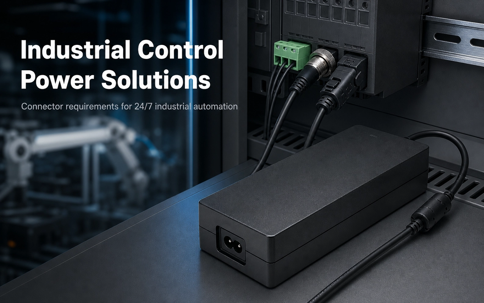
Industrial Control Power Solutions
Power solutions for PLC, CNC, servo and automation equipment
📖 Related Guides
✅ Related Certifications
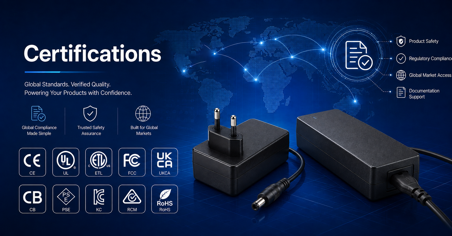
UL 62368-1 Safety Certification
Safety standard covering connector creepage/clearance, temperature rise, and strain relief requirements for IT/AV equipment power adapters.