
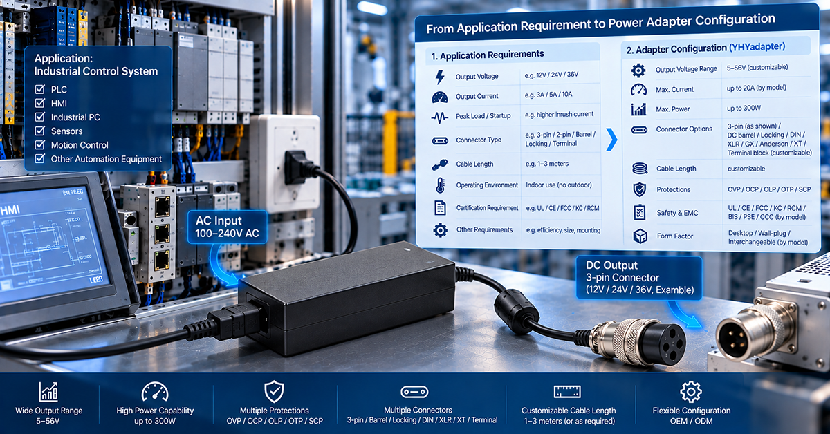
Power factor correction (PFC) is not optional for most industrial power supplies sold in global markets. IEC 61000-3-2 and its regional equivalents set limits on harmonic current emissions, and which limits apply depends on the equipment class and the market. Where those limits apply, active PFC is one common way to meet them. Active PFC is the dominant method for meeting these requirements while maintaining high efficiency across the load range.
This article covers the engineering principles, topology choices, regulatory landscape, and selection criteria that OEM design engineers need when specifying power supplies with active PFC for industrial applications.
What Is Power Factor Correction and Why Does Industry Need It?
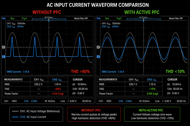
Power factor is the ratio of real power (watts) to apparent power (volt-amperes) in an AC circuit. In a purely resistive load, the power factor is 1.0 — current and voltage are in phase, and all drawn power performs useful work. In a conventional power supply without PFC, the input stage uses a bridge rectifier and bulk capacitor, drawing current only near the peak of each AC half-cycle. This creates a power factor of 0.5–0.65 and injects high-order harmonic currents into the mains.
The practical consequences of poor power factor in an industrial facility:
- Increased distribution losses: harmonic currents cause additional I²R losses in transformers, cables, and switchgear
- Reduced system capacity: transformers and generators must be oversized to deliver the same real power
- Equipment interference: harmonic currents can cause neutral overloading in three-phase systems, transformer overheating, and nuisance tripping of circuit breakers
- Regulatory non-compliance: products sold in the EU, China, Japan, and other regions must meet harmonic emission limits
Why This Matters
▸ An industrial power supply operating without PFC at 0.6 power factor draws 67% more apparent current than its real power requirement, increasing distribution costs in facility-scale deployments.
▸ Harmonic currents from multiple non-PFC supplies accumulate on shared distribution networks, creating power quality problems that affect other equipment.
▸ Regulatory compliance is market-specific—a power supply that passes EU harmonic limits may not automatically comply with Chinese GB 17625.1 or Japanese JIS C 61000-3-2 without design verification.
What OEMs Should Do Now
▸ An industrial power supply operating without PFC at 0.6 power factor draws 67% more apparent current than its real power requirement, increasing distribution costs in facility-scale deployments.
▸ Harmonic currents from multiple non-PFC supplies accumulate on shared distribution networks, creating power quality problems that affect other equipment.
▸ Regulatory compliance is market-specific—a power supply that passes EU harmonic limits may not automatically comply with Chinese GB 17625.1 or Japanese JIS C 61000-3-2 without design verification.
Active PFC vs Passive PFC — What Is the Difference?
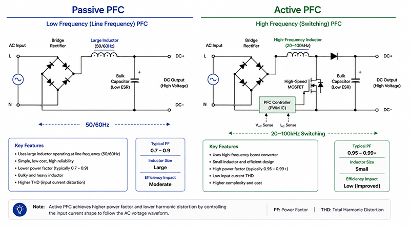
Passive PFC uses a large inductor (typically 10–30mH at 50/60Hz) placed between the rectifier and bulk capacitor to smooth the input current waveform. It achieves a power factor of 0.70–0.85 and is simple and reliable, but the inductor is physically large, heavy, and has fixed compensation that varies with load.
Active PFC uses a boost converter operating at 20–100kHz between the rectifier and bulk capacitor. It shapes the input current to follow the input voltage waveform, achieving a power factor of 0.95–0.99 across a wide load range.
| Parameter | Passive PFC | Active PFC |
| Power factor | 0.70–0.85 | 0.95–0.99 |
| THD (total harmonic distortion) | 30–80% | < 10% |
| Size (for 150W) | Large (50–100mm inductor) | Compact (20–40mm magnetic + PCB area) |
| Weight premium | +100–300g | +20–50g |
| Efficiency | 97–99% (inductor only) | 95–98% (switching losses) |
| Input voltage range | Narrow (±10%) | Wide (90–264VAC universal) |
| Cost premium (150W) | +$1–2 | +$3–6 |
| Regulatory compliance | Limited (may not meet IEC Class D) | Full compliance |
Why This Matters
▸ Active PFC enables universal input voltage range (90–264VAC), which passive PFC cannot achieve efficiently.
▸ In industrial equipment with multiple internal loads (motor drives, control logic, I/O modules), a single active PFC stage at the AC input corrects the entire system’s power factor rather than requiring per-load correction.
▸ The efficiency penalty of active PFC (1–3% loss in the boost stage) is typically offset by the elimination of downstream component oversizing caused by poor input power factor.
What OEMs Should Do Now
▸ For applications requiring universal input voltage (global product SKUs), active PFC is the only practical choice.
▸ For single-market, fixed-voltage industrial equipment operating below 75W, evaluate whether passive PFC or no PFC meets regional harmonic limits.
▸ Request total harmonic distortion (THD) data at 25%, 50%, 75%, and 100% load — an active PFC supply should maintain THD below 15% across this range.
What Active PFC Topologies Are Used in Industrial Power Supplies?
The most common active PFC topology for power supplies in the 75–1000W range is the boost converter operating in continuous conduction mode (CCM). It offers a good balance of efficiency, component stress, and control simplicity.
| Topology | Power Range | Peak Efficiency | Typical Application |
| CCM Boost PFC | 75–1000W | 96–98% | Most desktop and enclosed industrial supplies |
| Boundary/Transition Mode (CrM) PFC | 75–300W | 95–97% | Smaller industrial, LED drivers |
| Interleaved PFC | 500–3000W | 97–99% | High-power industrial, server supplies |
| Bridgeless PFC | 500–3000W | 97–99% | High-efficiency industrial, telecom |
| Vienna Rectifier (three-phase) | 1–10kW | 97–99% | Three-phase industrial drives |
The PFC stage typically operates at a switching frequency of 45–100kHz. The choice of switching frequency affects the size of the boost inductor, switching losses in the MOSFET, and electromagnetic interference (EMI) filter requirements. Higher frequencies reduce inductor size but increase switching losses and EMI filter complexity.
Why This Matters
▸ The PFC topology determines the power factor, THD, and efficiency characteristics at each load point — not all “active PFC” supplies perform identically.
▸ Industrial equipment operating at light load (standby, idle) should maintain power factor above 0.9. Some PFC controllers disable at light load, reverting to passive rectifier behavior with power factor dropping to 0.5–0.6.
▸ For three-phase industrial installations (common in factory automation, HVAC, pumps), Vienna rectifier topologies offer the highest efficiency but require more complex gate drive and control circuitry.
What OEMs Should Do Now
▸ Verify that the PFC stage remains active at your equipment’s typical operating load, not just at full rated output.
▸ For power levels above 500W, evaluate whether single-stage CCM or interleaved PFC provides better thermal distribution and component lifetime.
▸ Request conducted EMI test data with the PFC stage active — PFC switching creates noise in the 150kHz–10MHz range that must be managed by the input filter.
How Does Active PFC Affect Efficiency and Thermal Design?
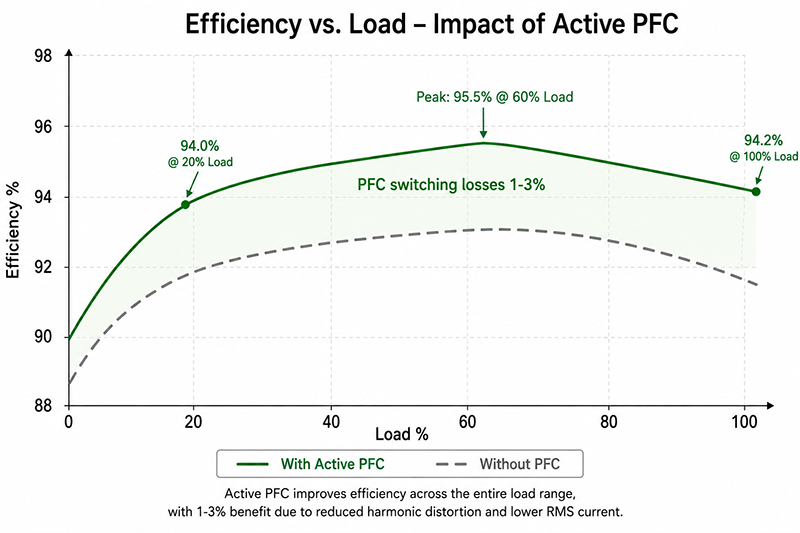
The PFC stage adds 1–3% efficiency loss compared to a non-PFC input stage. However, the overall system benefit is positive because downstream conversion stages (DC-DC) operate from a regulated high-voltage bus (typically 380–400VDC) instead of a rectified AC waveform that varies from 120–380V depending on line conditions.
The thermal impact of active PFC concentrates on:
- PFC MOSFET: Typically accounts for 40–50% of PFC stage losses. Junction temperature must be maintained below 110°C for reliable operation.
- Boost diode (or SiC diode): Fast-recovery or silicon carbide diodes are used to minimize reverse recovery losses, which are significant at CCM switching frequencies.
- PFC inductor: Core losses (ferrite or powdered iron) plus winding copper losses account for 25–30% of PFC stage losses. The inductor is often the hottest magnetic component in the power supply.
- Input bridge rectifier: With active PFC, the rectifier conducts over a wider angle, reducing peak current stress compared to non-PFC designs but increasing average conduction losses.
Why This Matters
▸ In a 120W industrial power supply, the PFC stage dissipates approximately 2–4W of heat that must be managed by the enclosure thermal design—typically 15–25% of total power supply losses.
▸ Silicon carbide (SiC) diodes in the PFC stage virtually eliminate reverse recovery losses, improving efficiency by 0.3–0.8% and reducing PFC stage temperature by 5–10°C.
▸ The PFC boost inductor is often the acoustically noisiest component (audible 20–100kHz whine). Encapsulation or frequency dithering may be required for noise-sensitive industrial environments.
What OEMs Should Do Now
▸ Request vendor data for PFC stage losses at the specific load point where your equipment operates, not just the headline efficiency number.
▸ For noise-sensitive environments (medical, laboratory, audio), specify power supplies with frequency dithering or soft-switching PFC to minimize audible noise.
▸ Evaluate whether a higher-wattage power supply operating at 60–70% load provides better overall thermal margin than a lower-wattage supply running near its PFC stage’s thermal limit.
How to Select a Power Supply with the Right PFC for Your Application
Step 1 — Determine regulatory requirements
- EU: IEC/EN 61000-3-2 (mandatory for CE marking, >75W Class A/D)
- China: GB 17625.1 (CCC certification, harmonized with IEC 61000-3-2)
- Japan: JIS C 61000-3-2 (voluntary but market-expected over 75W)
- USA: No federal PFC mandate, but ENERGY STAR and 80 PLUS programs incentivize PFC for efficiency above 75–100W
- Global OEM: Meeting IEC 61000-3-2 is the most practical baseline for multi-market products
Step 2 — Determine power factor requirements
- General industrial equipment: PF > 0.90 at full load
- Power-sensitive grid-connected equipment (UPS, chargers): PF > 0.95
- Three-phase industrial drives: PF > 0.95 with THD < 10%
- Low-power auxiliary circuits (below 75W): PFC may not be required; verify per market
Step 3 — Verify with vendor data
- Power factor curve (10–100% load, nominal input voltage)
- THD curve (same load range)
- Efficiency at load point with and without PFC stage engaged
- PFC hold-up time: typical requirement is 10–20ms at full load for industrial equipment
- EMI test report with PFC active
Why This Matters
▸ Selecting an active PFC power supply for equipment that only operates in markets without PFC mandates adds cost and complexity without benefit.
▸ A power supply that meets PF > 0.95 at full load may drop to PF < 0.8 at 20% load — verify the PF curve at your actual operating point.
▸ Certifications available depending on model, application and target market. Not all PFC-equipped supplies carry the same harmonic compliance certifications.
What OEMs Should Do Now
▸ Map your target markets against harmonic emission requirements before selecting PFC type.
▸ Request the PF and THD curves from at least two vendors to establish a benchmark for your power supply specification.
▸ Include PFC hold-up time in your power supply specification — a well-designed PFC stage stores enough energy in the DC bus capacitor to maintain output for at least 10ms during an AC cycle dropout.
CONCLUSION
Active PFC is the dominant method for achieving power factor above 0.95 and meeting IEC 61000-3-2 harmonic limits in industrial power supplies. The choice of PFC topology, switching frequency, and component selection directly affects efficiency, thermal design, EMI, and cost. OEM engineers should evaluate power factor, THD, and efficiency across the full load range rather than at a single operating point, and verify regulatory compliance for each target market.
Certifications available depending on model, application and target market.
Frequently Asked Questions
What is the difference between active and passive PFC?
Passive PFC uses passive components to improve the input current shape; active PFC uses an additional switching stage to shape the current so it tracks the input voltage. Active approaches generally achieve a higher power factor and better behaviour across the load range.
When is power factor correction required?
It depends on the applicable harmonic-current standard, the equipment class, and the target market. Applicability is established against the standard in force for the product and market, rather than from a single general rule.
Does active PFC improve efficiency?
Power factor and efficiency are different metrics, reported separately and measured differently. PFC addresses the input current shape and harmonic content; a design can be efficient with a modest power factor, or the reverse.
How does PFC affect thermal design?
An active PFC stage adds switching losses and components inside the supply, which appear in the thermal budget. Thermal design should account for the supply’s measured behaviour at the relevant load, not only for the headline efficiency figure.
How do I confirm PFC on a specific model?
Confirm from the model’s datasheet and specification, by model and target market. Configuration and certification availability are confirmed per model rather than assumed across a range.
Related Resources
🔌 Related Products
🏭 Related Applications

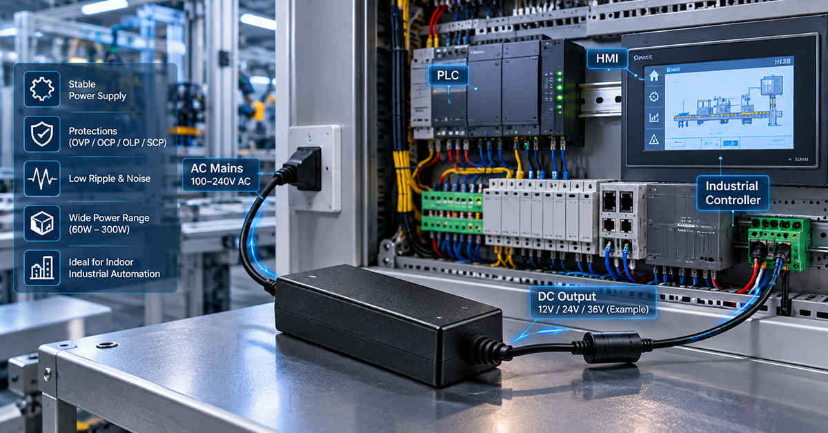
Industrial Control Power Solutions
Power solutions for PLC, CNC, servo and automation equipment
📖 Related Guides
✅ Related Certifications
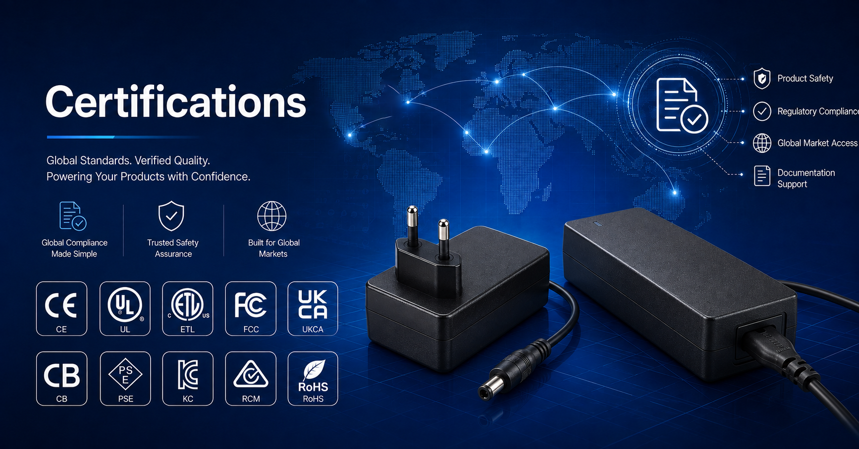
UL 62368-1 Safety Certification
Safety standard covering connector creepage/clearance, temperature rise, and strain relief requirements for IT/AV equipment power adapters.