
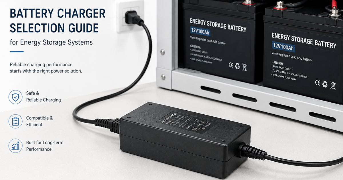
YHYadapter product positioning: YHYadapter provides regulated constant-voltage (CV) AC/DC power adapters. Dedicated battery chargers with chemistry-specific charging profiles, multi-stage CC/CV algorithms, and BMS communication are available from specialized battery charger manufacturers. The charging profile and battery chemistry information in this guide serves as industry reference for OEMs designing ESS power architecture.
Battery charging is a fundamental function of any energy storage system (ESS). The AC/DC charger—the power supply that converts AC mains power to regulated DC for battery charging—must deliver the correct charging profile for the battery chemistry, manage the charge current and voltage within safe limits, and operate reliably over the system’s service life. Unlike general-purpose power adapters that deliver a fixed output voltage, battery chargers must coordinate with the battery management system (BMS) to implement charge termination, temperature compensation, and fault detection.
This guide covers the selection criteria for AC/DC battery chargers used in energy storage systems: battery chemistry requirements, charging profiles, AC/DC architecture, form factors, and OEM considerations.
Battery Chemistry Charging Requirements
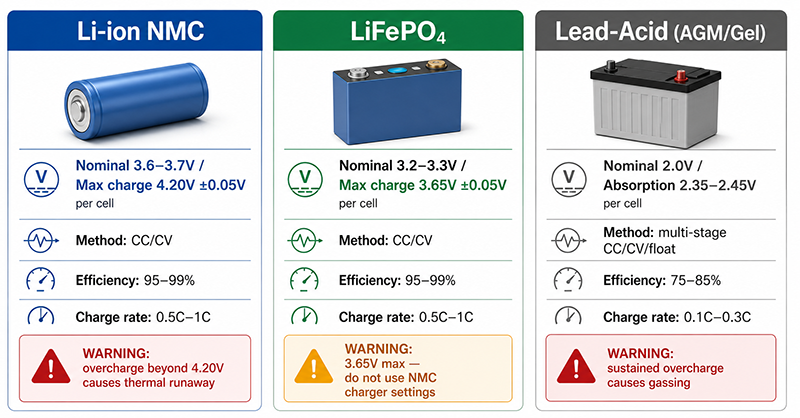
The charging requirements of an energy storage system are determined by the battery chemistry. The three most common chemistries in ESS applications are lithium-ion (Li-ion), lithium iron phosphate (LiFePO4), and lead-acid (including AGM and gel types).
| Parameter | Li-ion (NMC) | LiFePO4 | Lead-Acid (AGM/Gel) |
|---|---|---|---|
| Nominal cell voltage | 3.6–3.7V | 3.2–3.3V | 2.0V |
| Maximum charge voltage (per cell) | 4.20V (±0.05V) | 3.65V (±0.05V) | 2.35–2.45V (absorption) |
| Recommended charge method | CC/CV | CC/CV | CC/CV (multi-stage) |
| Charge efficiency | 95–99% | 95–99% | 75–85% |
| Typical C-rate (charge) | 0.5C–1C | 0.5C–1C | 0.1C–0.3C |
| Temperature compensation | Required (0–45°C charge) | Required (0–55°C charge) | Required |
| Charge termination | Current drops to ~3–5% of rated | Current drops to ~3–5% of rated | Voltage hold + current drop |
CC/CV Charging Profile
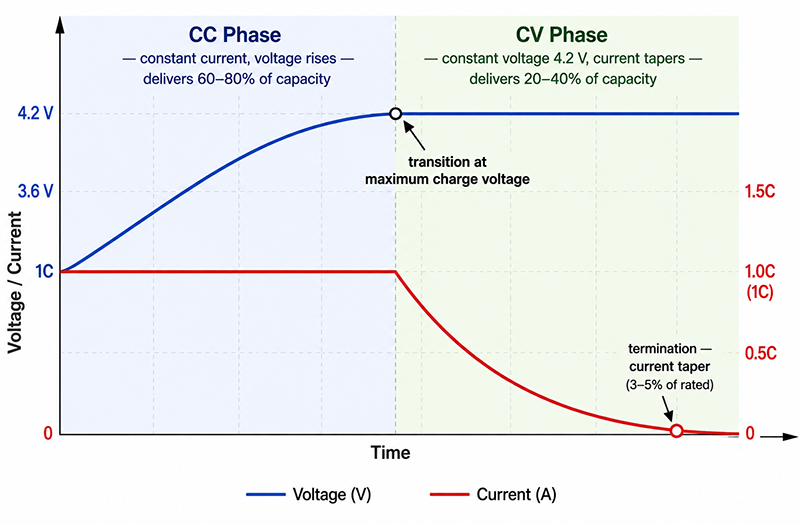
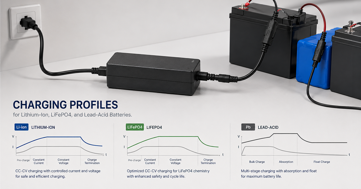
The standard charging method for lithium-based batteries is constant current / constant voltage (CC/CV):
- Constant Current (CC) phase: The charger delivers a constant current (typically 0.5C–1C) until the battery reaches its maximum charge voltage.
- Constant Voltage (CV) phase: The charger maintains the maximum charge voltage while the current gradually decreases as the battery approaches full charge.
- Termination: Charging terminates when the current drops below a threshold (typically 3–5% of the rated charge current).
Lead-acid batteries use a multi-stage charging profile: bulk (constant current), absorption (constant voltage), float (lower constant voltage for maintenance), and equalization (periodic higher voltage for cell balancing).
Battery Pack Voltages
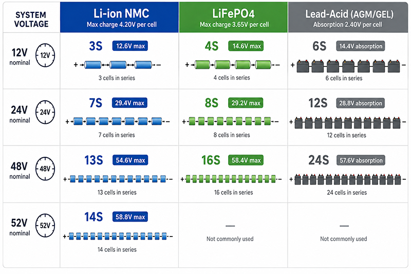
| System Voltage | Li-ion (NMC) Configuration | LiFePO4 Configuration | Lead-Acid Configuration |
|---|---|---|---|
| 12V nominal | 3S (12.6V max) | 4S (14.6V max) | 6S (14.4V absorption) |
| 24V nominal | 7S (29.4V max) | 8S (29.2V max) | 12S (28.8V absorption) |
| 48V nominal | 13S (54.6V max) | 16S (58.4V max) | 24S (57.6V absorption) |
| 52V nominal | 14S (58.8V max) | — | — |
Why This Matters
- Overcharging a Li-ion battery beyond 4.20V/cell can cause thermal runaway. The charger must have accurate voltage regulation (±0.05V/cell or better) and multiple layers of overvoltage protection.
- Charging a LiFePO4 battery with a Li-ion charger (designed for 4.20V/cell) will overvoltage the LiFePO4 cells (maximum 3.65V/cell), causing damage or failure.
- Lead-acid batteries have lower charge efficiency (75–85%) compared to lithium (95–99%), meaning more heat is generated during charging and the charger must be sized to account for the energy lost as heat.
OEM Actions
- Select a charger with the correct charging profile for the battery chemistry. Do not assume compatibility between different lithium chemistries or between lithium and lead-acid.
- Verify the charger’s voltage regulation accuracy at the battery’s maximum charge voltage. A ±1% tolerance on a 58.4V LiFePO4 system allows ±0.58V variation across 16 cells (±36mV/cell).
- For lead-acid systems, select a multi-stage charger with bulk, absorption, float, and (if needed) equalization modes.
AC/DC Charger Architecture
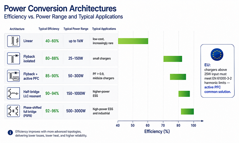
The AC/DC battery charger converts AC mains power to the regulated DC output required for battery charging. The charger architecture determines its efficiency, power factor, size, and cost.
| Architecture | Power Range | Typical Efficiency | Typical PF | Best For |
|---|---|---|---|---|
| Linear (transformer + rectifier) | Up to 1kW | 40–60% | 0.5–0.7 | Low-cost, low-power; increasingly rare |
| Flyback (isolated) | 25–150W | 80–88% | 0.5–0.7 (passive) | Small battery chargers, portable equipment |
| Flyback with active PFC | 50–300W | 85–90% | >0.9 | Midsize chargers requiring PF compliance |
| Half-bridge / LLC (resonant) | 150–1000W | 90–94% | >0.9 (with PFC stage) | Higher-power ESS chargers, good efficiency |
| Phase-shifted full bridge (PSFB) | 500–3000W | 92–96% | >0.9 (with PFC) | High-power ESS and industrial chargers |
Charger Configurations
| Configuration | Description | Typical Applications |
|---|---|---|
| Integrated charger (inside ESS enclosure) | Charger electronics built into the battery system | Home ESS, UPS, portable power stations |
| External charger (separate enclosure) | Standalone charger connected to battery via DC cable | Industrial ESS, telecom, backup power |
| Multi-channel charger | Multiple independent charging outputs | Large ESS with multiple battery strings |
| Bidirectional (inverter + charger) | Charger and inverter in one unit | Home ESS with solar (hybrid inverter) |
Why This Matters
- For ESS applications above 25W input power in EU markets, the charger must meet EN 61000-3-2 harmonic limits. Active PFC is a common method for compliance.
- Higher charger efficiency reduces heat generation, which is important when the charger is integrated into the ESS enclosure alongside batteries that are sensitive to elevated temperature.
- External chargers offer better thermal isolation from the battery enclosure but require DC cabling that must be sized for the charge current.
OEM Actions
- Determine the required charger power based on the battery capacity and desired charge time. A 100Ah 48V battery charged at 0.5C requires a charger capable of 50A at 58.4V (~2.9kW).
- For chargers above 25W, specify active PFC for EU markets. For higher-power chargers (>500W), LLC or PSFB architecture offers better efficiency.
- For integrated chargers, consider the thermal impact of charger losses on the battery enclosure temperature. An integrated 2kW charger at 90% efficiency dissipates 200W inside the enclosure.
Charger Selection Criteria Framework
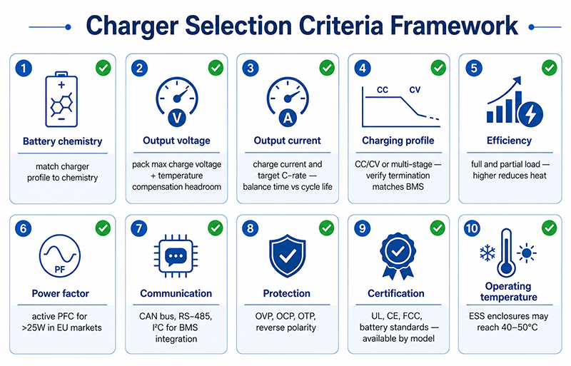
When selecting an AC/DC battery charger for an ESS application, use the following criteria:
| Criterion | What to Evaluate | Suggested Approach |
|---|---|---|
| Battery chemistry | Li-ion, LiFePO4, lead-acid, or other | Match charger profile to chemistry specification |
| Output voltage | Battery pack maximum charge voltage | Allow headroom for temperature compensation |
| Output current | Charge current (A) and target C-rate | Balance charge time against battery cycle life |
| Charging profile | CC/CV, multi-stage CC/CV/float | Verify termination method matches BMS capability |
| Efficiency | Full-load and partial-load efficiency | Higher efficiency reduces heat and energy cost |
| Power factor | PF at rated output | Active PFC for >25W in EU markets |
| Communication interface | CAN bus, RS-485, I²C (for BMS integration) | Enables coordinated charge management |
| Protection features | OVP, OCP, OTP, reverse polarity | Multiple protection layers for safety |
| Certification | UL, CE, FCC, applicable battery standards | Available by model |
| Operating temperature | Ambient range and derating | ESS enclosures may reach 40–50°C ambient |
Why This Matters
- The charger’s output voltage must accommodate the full charge voltage of the battery pack plus temperature compensation. A LiFePO4 48V pack charging at 58.4V in cold temperatures may need up to 60V.
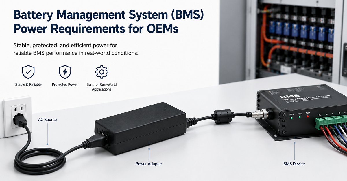
- BMS communication enables the charger to respond to BMS commands (charge enable/disable, current limit) for coordinated charging.
- Reverse polarity protection is essential for external chargers where the user connects the DC output to the battery. A charger without this protection can be damaged or cause a fire if the output leads are reversed.
OEM Actions
- Create a charger specification sheet that includes all criteria above, with specific values for the battery chemistry, pack configuration, and target charge time.
- Verify the charger’s output voltage range covers the battery pack’s full charge voltage range, including temperature compensation adjustments.
- If BMS communication is required, verify the communication protocol compatibility (CAN bus version, baud rate, message format) between the charger and the BMS.
Q: Can I use a standard power adapter to charge a Li-ion battery?
A: A standard CV power adapter lacks the CC/CV charging profile required for lithium batteries. Without current limiting in the CC phase, the battery may draw excessive current, causing overheating or damage. A dedicated battery charger with CC/CV output is required for lithium battery charging.
Q: What is the difference between a battery charger and a power supply?
A: A power supply provides a regulated output voltage at up to its rated current. A battery charger provides a charging profile (typically CC/CV) that limits current during initial charging, holds the voltage at the battery’s maximum charge voltage, and terminates charging when the battery is full. A charger is a specialized power supply designed for battery charging.
Q: How long does it take to charge an ESS battery?
A: Charge time depends on the battery capacity and the charger’s current rating. A 100Ah battery charged at 0.5C (50A) reaches full charge in approximately 2.5 hours accounting for the CV phase taper. At 0.2C (20A), the same battery takes approximately 6 hours. Faster charging (higher C-rate) reduces battery cycle life.
Conclusion
Battery charger selection for energy storage systems requires matching the charger’s output characteristics to the battery chemistry requirements. The charging profile (CC/CV for lithium, multi-stage for lead-acid), voltage accuracy, current rating, communication interface, and protection features must all be coordinated with the battery pack and BMS. The charger’s AC/DC architecture determines its efficiency, power factor, and thermal characteristics. Dedicated battery chargers with chemistry-specific charging profiles and BMS integration are available from specialized manufacturers.
Related Resources
🔌 Related Products
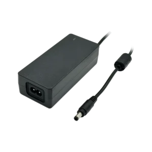
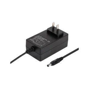
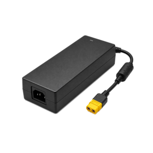
12.6V 4A 50W Li-Ion Charger (3-series Li-Ion charging)
12.6V 4A CC/CV Li-Ion charger for 3-series battery packs
🏭 Related Applications
📖 Related Guides
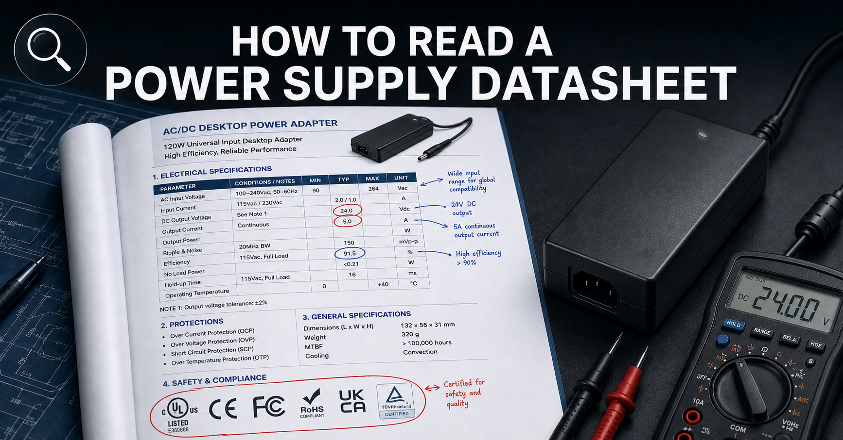
How to Read a Power Supply Datasheet
Learn how to evaluate connector specifications in a datasheet — current ratings, derating curves, certification verification.
✅ Related Certifications
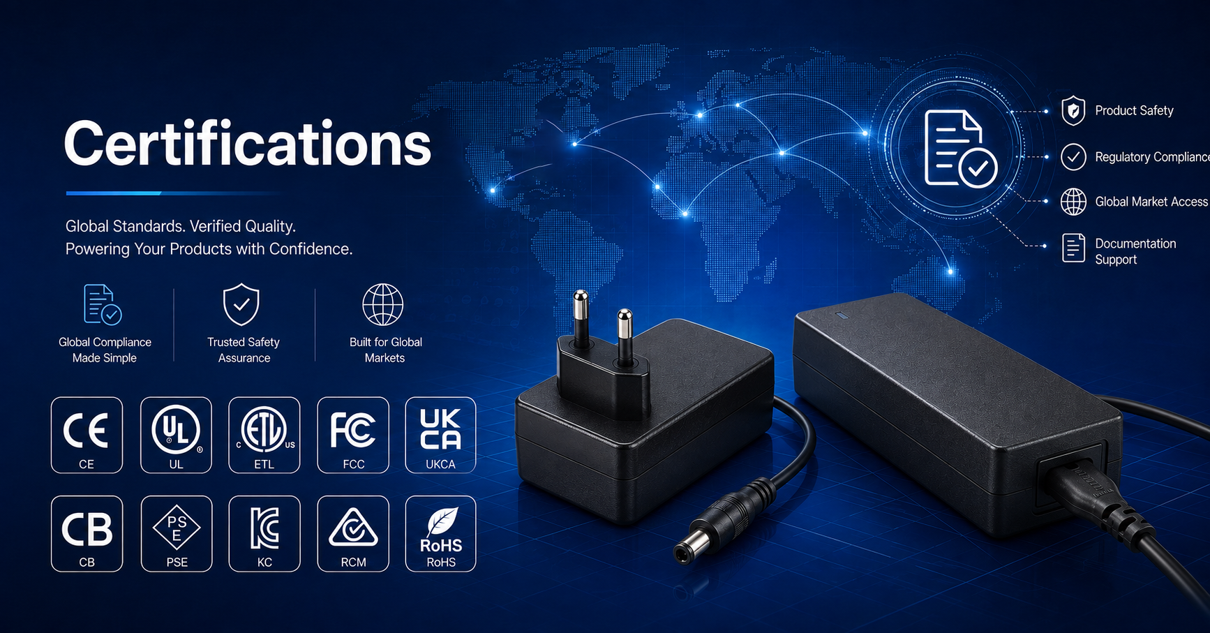
UL 62368-1 Safety Certification
Safety standard covering connector creepage/clearance, temperature rise, and strain relief requirements for IT/AV equipment power adapters.