
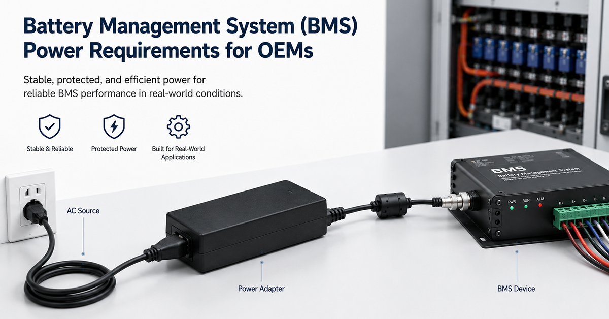
The battery management system (BMS) is the intelligence behind every lithium-based energy storage system. It monitors cell voltages, temperatures, and currents; controls contactors; communicates with the charger and inverter; and implements the safety algorithms that prevent overcharge, over-discharge, and thermal runaway. The BMS itself requires a reliable power supply—one that remains operational even when the main battery contactors are open, that provides isolated power for high-side cell monitoring, and that consumes minimal current to avoid draining the battery during storage.
This guide covers the power supply requirements for BMS in energy storage applications: power consumption by BMS function, isolated power design for cell monitoring, auxiliary power supply considerations, wake and sleep circuitry, and OEM integration guidance.
BMS Power Consumption by Function
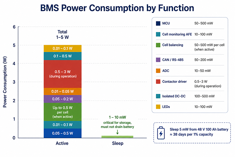
A BMS module consists of several functional blocks, each with distinct power requirements.
| BMS Function | Typical Power | Voltage | Notes |
|---|---|---|---|
| Main MCU | 50–500mW | 3.3V, 1.8V | Varies with processing load and features |
| Cell monitoring AFE (analog front end) | 10–100mW | 3.3V, 5V | Consumes more power during active cell balancing |
| Cell balancing (passive) | 50–500mW per cell (on) | Battery cell voltage | Only active during balancing; resistors dissipate cell energy |
| CAN / RS-485 transceiver | 50–200mW | 3.3V, 5V, or direct from bus | Active only during communication |
| ADC (voltage, current, temperature) | 10–50mW | 3.3V, 5V | Continuous or periodic measurement |
| Contactor coil driver | 500mW–3W (during contactor operation) | 12V or battery voltage | Only active during contactor open/close transition; no hold power for magnetic-latching contactors |
| Isolated DC-DC converter (cell monitoring) | 100–500mW | Battery voltage to isolated rail | Continuous operation; major component of BMS idle power |
| LED indicators | 10–100mW (total) | 3.3V | Optional, can be disabled in sleep |
| Total BMS (active) | 1–5W | Depends on cell count, balancing, and features | |
| BMS (sleep) | 1–10mW | Critical for storage; must not drain battery |
Always-On Power Budget
The BMS’s always-on power consumption—primarily the MCU in low-power mode, isolated DC-DC converter, and voltage monitoring—determines how long the BMS can remain connected to the battery without draining it during storage or transport.
A BMS consuming 5mW continuously from a 48V 100Ah battery (4,800Wh) would take approximately 38 days to drain 1% of the battery’s capacity. For applications requiring extended storage, the BMS should enter an ultra-low-power state with consumption below 1mW.
Why This Matters
- The BMS must remain powered to monitor cell voltages and respond to fault conditions. If the BMS loses power, the battery may enter an unprotected state.
- Passive cell balancing dissipates energy as heat. Active balancing (charge transfer between cells) is more efficient but adds cost and complexity.
- The BMS’s always-on power consumption must be accounted for in the ESS’s self-consumption budget, particularly for systems that remain idle for extended periods.
OEM Actions
- Calculate the BMS’s total power consumption in all operating modes (active, balancing, sleep, transport). Select power components rated for the full operating range.
- For the always-on power supply, select a DC-DC converter with high efficiency at low loads. A converter optimized for 10W output may be inefficient at 100mW.
- Design the BMS to enter a sleep state (≤1mW) during storage or transport, with wake on button press, charger connection, or BMS command.
Isolated Power for High-Side Cell Monitoring
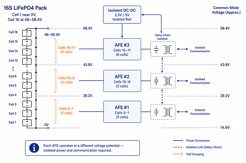
In a battery pack, the BMS must monitor each series cell. The cell monitoring circuits for cells above the pack negative terminal operate at different voltage potentials, requiring isolated power and communication.
The Isolation Challenge
In a 48V LiFePO4 battery (16S), the bottom cell (cell 1) has a voltage near 0V relative to pack negative. The top cell (cell 16) operates at 48–58.4V relative to pack negative. The BMS must measure each cell voltage difference accurately while handling the common-mode voltage difference between cells.
Power Supply Architecture for Cell Monitoring
| Architecture | Description | Power Consumption | Cost | Best For |
|---|---|---|---|---|
| Stackable AFE with daisy-chain | Each AFE (analog front end) measures 4–12 cells; communicates via capacitive or transformer isolation | 10–50mW per AFE | Moderate | Medium to large ESS (12–48 cells) |
| Individual isolated DC-DC per AFE | Each AFE has its own isolated power supply | 50–200mW per AFE | Higher | Systems requiring high noise immunity |
| Battery-powered AFE (self-powered) | Each AFE is powered from its own cell group | 10–30mW per AFE | Lower | Small packs with limited cell count |
Isolated DC-DC Converter Requirements
| Parameter | Typical Requirement | Notes |
|---|---|---|
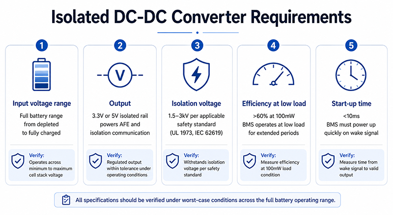
| Input voltage range | Full battery voltage range | Must operate from depleted to fully charged |
| Output voltage | 3.3V or 5V (isolated) | Powers AFE and isolation communication |
| Isolation voltage | 1.5–3kV (per applicable safety standard) | Depends on system voltage and safety standard |
| Efficiency at low load | >60% at 100mW | BMS may operate at low load for extended periods |
| Start-up time | <10ms | BMS must power up quickly when wake signal is received |
Why This Matters
- Without properly isolated power for cell monitoring, common-mode voltage differences can cause inaccurate cell voltage readings, leading to incorrect state-of-charge estimation and potential overcharge.
- The isolated DC-DC converter is a continuous power consumer. Its quiescent current contributes significantly to the BMS’s always-on power consumption.
- Insufficient isolation voltage can lead to breakdown during surge or fault conditions, potentially causing arcing and fire within the battery pack.
OEM Actions
- Select an AFE architecture appropriate for the battery pack voltage and cell count. Daisy-chain AFEs with capacitive isolation are common for 48V systems.
- Verify the isolated DC-DC converter’s isolation voltage exceeds the requirements of the applicable safety standard (UL 1973, IEC 62619, etc.).
- Measure the BMS’s always-on power consumption, including the isolated power supply’s quiescent current, under worst-case conditions.
Auxiliary Power Supply and Wake Circuitry
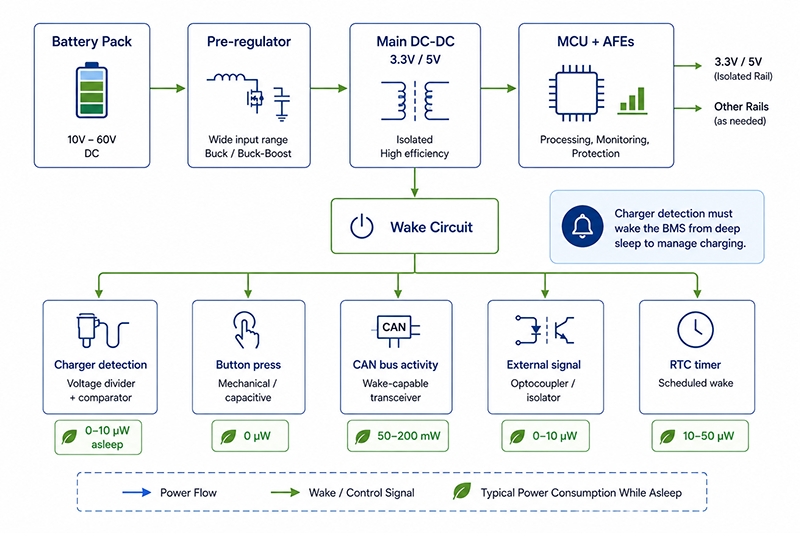
The BMS requires a power supply architecture that supports multiple operating states and responds to wake events from the battery, charger, or system controller.
Auxiliary Power Supply Architecture
Battery Pack → Pre-regulator → Main DC-DC (3.3V, 5V) → MCU + AFEs
                                    ↓
                              Wake Circuit
                                    ↓
                         Charger Detection / Button / CAN
Wake Event Sources
| Wake Source | Description | Power When Asleep | Typical Implementation |
|---|---|---|---|
| Charger connection | Charger applies voltage to battery terminals | 0–10µW | Voltage divider + comparator |
| Button press | User presses BMS wake button | 0µW | Mechanical switch or capacitive touch |
| CAN bus activity | System controller sends CAN message | 50–200mW (CAN transceiver) | CAN wake-up capable transceiver |
| External signal | System controller sends discrete signal | 0–10µW | Optocoupler or digital isolator |
| Timer | RTC wakes BMS at scheduled interval | 10–50µW | RTC with alarm output |
Charger Detection
The BMS must detect when a charger is connected, even when the BMS is in sleep state. Detection is typically implemented with a voltage divider connected to the battery terminals (through the charger path) that triggers a comparator or the MCU’s wake-up pin when voltage rises above the battery’s resting voltage.
Why This Matters
- A BMS that cannot detect charger connection while asleep will not wake up to manage charging, leaving the battery unprotected during the most dangerous operation (charging).
- The wake circuit must consume negligible power (ideally <10µW) to avoid draining the battery during storage.
- A mechanical wake button provides a reliable wake method that consumes zero power when not pressed, useful for initial system startup and maintenance.
OEM Actions
- Design the BMS to wake from sleep automatically when a charger is connected, even if the BMS was in deep sleep. Verify charger detection works at the charger’s minimum output voltage.
- Include a manual wake method (button or jumper) for initial system commissioning and fault recovery.
- Verify the wake circuit’s power consumption in sleep mode and ensure it does not exceed the battery’s acceptable self-discharge rate during storage.
BMS Power Supply Integration Checklist
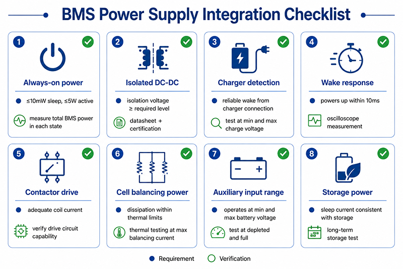
| Area | Check | Verification |
|---|---|---|
| Always-on power | BMS consumes ≤10mW in sleep, ≤5W active | Measure total BMS power in each state |
| Isolated DC-DC | Isolation voltage ≥ required level | Manufacturer datasheet + certification |
| Charger detection | Reliable wake from charger connection | Test at minimum and maximum charge voltage |
| Wake response time | BMS powers up within 10ms of wake event | Oscilloscope measurement |
| Contactor drive | Adequate current for contactor coil | Verify coil drive circuit capability |
| Cell balancing power | Passive balancing dissipation within thermal limits | Thermal testing at maximum balancing current |
| Auxiliary input range | BMS operates at minimum and maximum battery voltage | Test at depleted and fully charged voltage |
| Storage power | BMS sleep current consistent with storage requirements | Long-term storage test or calculation |
Useful Links
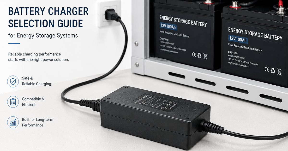
Related article: Battery Charger Selection Guide →
Related article: Charging Profiles Guide →
Q: Does the BMS need its own power supply separate from the battery pack?
A: The BMS is typically powered from the battery pack itself, using a pre-regulator that provides a stable voltage (12V or similar) for the BMS’s internal DC-DC converters. This ensures the BMS is powered whenever the battery has charge. An external auxiliary power supply is not typically needed, but the BMS should have a low-power sleep mode for extended storage.
Q: How does the BMS power itself when the main contactors are open?
A: The BMS is powered directly from the battery terminals, ahead of the main contactors (or through a dedicated pre-charge circuit). This allows the BMS to remain operational and monitor cell voltages even when the battery’s output is disconnected from the load.
Q: What happens if the BMS loses power while the battery has charge?
A: If the BMS loses power, cell monitoring and protection functions are disabled. The battery may enter an unprotected state. Most ESS designs include a BMS power supply with under-voltage lockout to prevent operation below the battery’s minimum voltage. If the battery voltage drops below the BMS’s minimum operating voltage, the BMS shuts down and the battery should be disconnected from the load to prevent deep discharge.
Conclusion
The BMS power supply is a critical component of any lithium-based energy storage system. It must provide reliable, isolated power for the MCU, cell monitoring AFEs, contactor drive, and communication interfaces. The power architecture must support active, sleep, and storage states with minimal power consumption in each. Wake circuitry must detect charger connection, button press, or system commands to transition the BMS from sleep to active state. Designing the BMS power supply for the full battery voltage range, isolation requirements, and low quiescent current is essential for reliable ESS operation.
Related Resources
🔌 Related Products
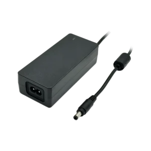
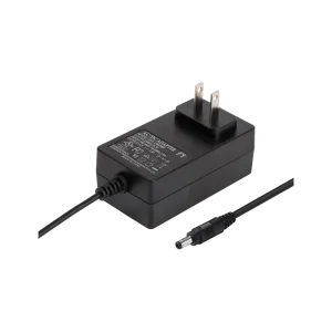
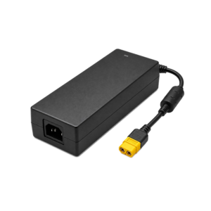
12.6V 4A 50W Li-Ion Charger (3-series Li-Ion charging)
12.6V 4A CC/CV Li-Ion charger for 3-series battery packs
🏭 Related Applications
📖 Related Guides
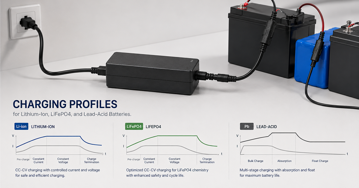
Charging Profiles Guide
Charging curves for Li-Ion, LiFePO4 and lead-acid
Read Guide →
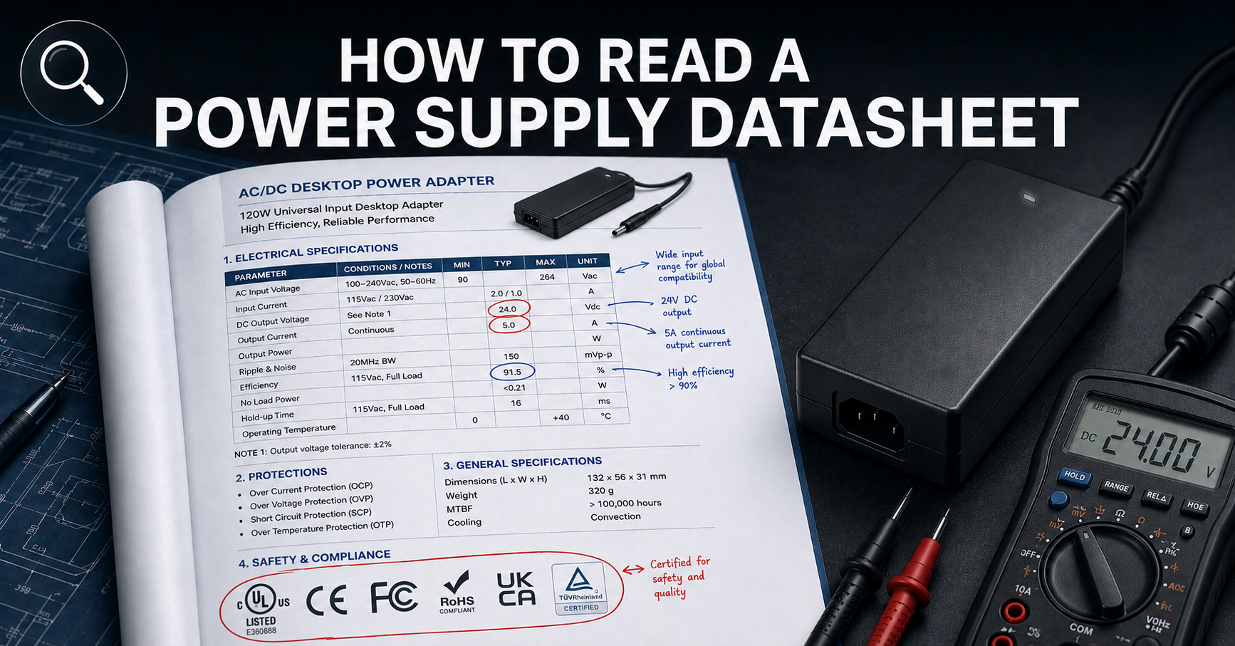
How to Read a Power Supply Datasheet
Learn how to evaluate connector specifications in a datasheet — current ratings, derating curves, certification verification.
✅ Related Certifications
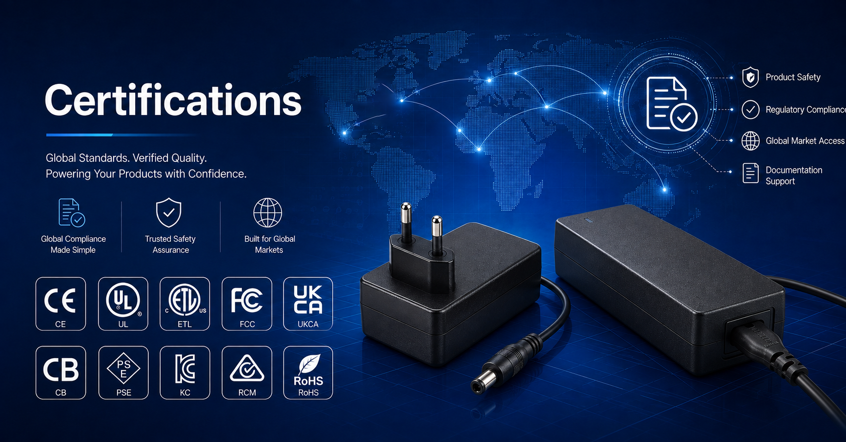
UL 62368-1 Safety Certification
Safety standard covering connector creepage/clearance, temperature rise, and strain relief requirements for IT/AV equipment power adapters.