
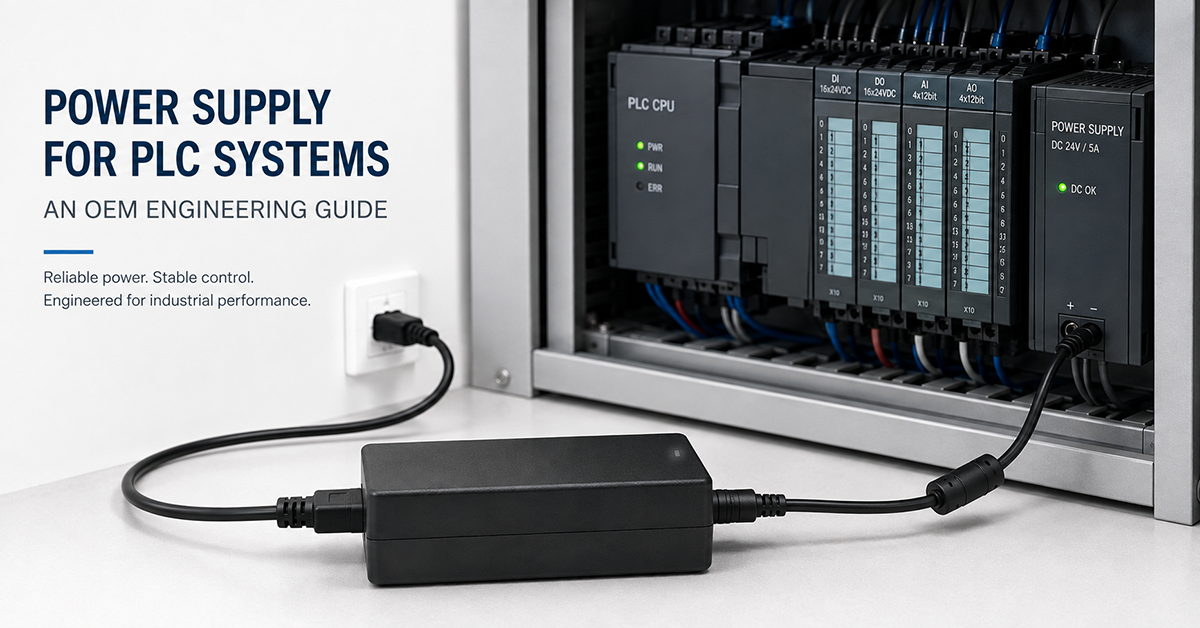
The power supply is a critical yet frequently undervalued component in a PLC-based control system. While PLC processors and I/O modules receive the most attention during system design, an underspecified or poorly matched power supply is the root cause of an estimated 30–40% of field failures in industrial control panels, based on industry reliability surveys and warranty data analysis.
This article covers the engineering requirements for power supplies used in PLC systems: voltage and current requirements by PLC platform, hold-up time specifications, noise immunity, DIN rail mounting considerations, and practical selection criteria for OEM control system designers.
What Voltage and Current Do PLC Systems Require?
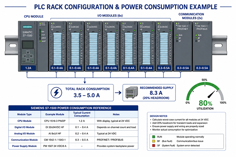
Most industrial PLCs operate on 24VDC, though some legacy platforms use 5V or 12V for internal logic and analog circuits. A typical PLC system consists of:
- Processor/CPU module: 24VDC, 0.5–2.5A depending on processing power and onboard I/O
- Digital I/O modules: 24VDC (input power), typically 0.05–0.3A per module for internal logic (external sensor/actuator power is separate)
- Analog I/O modules: 24VDC, typically 0.1–0.4A per module
- Communication modules: 24VDC, typically 0.2–0.5A per module (EtherNet/IP, Profinet, Modbus TCP)
- Special-function modules (motion control, vision): 24VDC, 0.5–2.0A per module
| PLC Platform | CPU Power | Typical System (8 slot rack) | Recommended Supply |
| Siemens S7-1200 | 24V, 0.8A | 24V, 2.0–3.0A | 24V, 5.0A (120W) |
| Siemens S7-1500 | 24V, 1.2A | 24V, 3.0–5.0A | 24V, 8.3A (200W) |
| Allen-Bradley CompactLogix | 24V, 1.5A | 24V, 3.5–6.0A | 24V, 10A (240W) |
| Allen-Bradley ControlLogix | 24V, 2.0A | 24V, 5.0–8.0A | 24V, 10–15A (240–360W) |
| Mitsubishi FX5U | 24V, 0.5A | 24V, 1.5–3.0A | 24V, 3.0A (72W) |
| Omron NJ/NX | 24V, 0.7A | 24V, 2.0–4.0A | 24V, 5.0A (120W) |
| Beckhoff CX series | 24V, 1.0A | 24V, 2.5–5.0A | 24V, 8.0A (192W) |
External field power (sensors, actuators, output modules) must be calculated separately. A typical control cabinet with 32 digital inputs (24V, 10mA each), 32 digital outputs (24V, 0.5A each), and 8 analog channels (24V, 40mA each) requires approximately 18.5A of additional 24V field power beyond the PLC rack power.
Why This Matters
- Undersizing the PLC rack supply causes intermittent resets, communication errors, and corrupted I/O states — failures that are difficult to diagnose in the field.
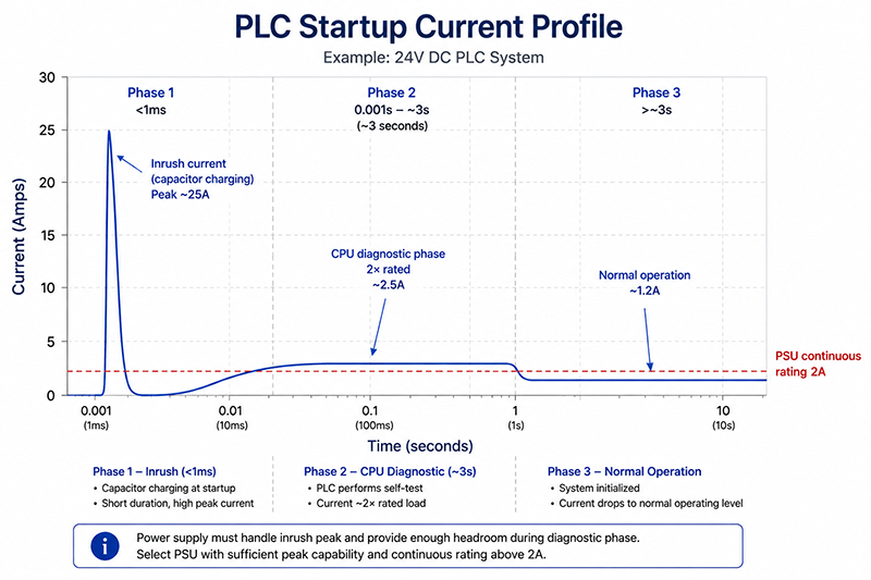
- PLC power consumption is not constant — CPU modules draw 1.5–2× their rated current during startup (power-on diagnostic phase), which lasts 1–5 seconds.
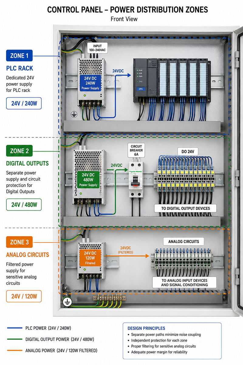
- Field power (sensors, outputs) should be supplied by a separate power supply or a separately fused branch from the main 24V supply to prevent actuator faults from affecting PLC logic.
What OEMs Should Do Now
- Calculate total PLC cabinet power as: P_rack = Σ(all module internal consumption) + P_field × 1.2 margin
- Always specify a power supply with at least 20% headroom above calculated peak demand.
- Use separate power supply branches for: (1) PLC rack, (2) digital outputs, (3) analog circuits (if high precision is required).
What Is Hold-Up Time and Why Does It Matter for PLCs?
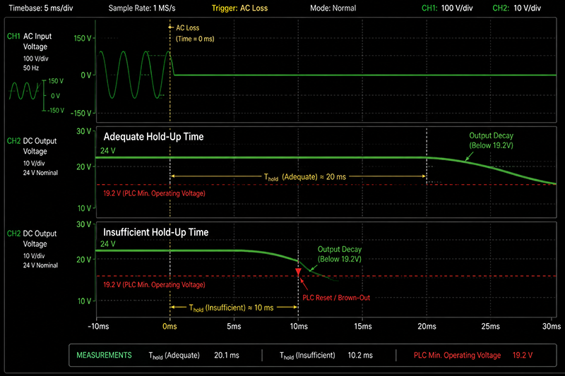
Hold-up time is the duration a power supply can maintain regulated output after the AC input is interrupted. For PLC systems, hold-up time is critical because:
- A power interruption of 10–20ms can cause a PLC CPU to reset if the supply voltage drops below its minimum operating threshold.
- PLC program execution state is lost on reset, requiring the full startup sequence (typically 2–30 seconds depending on program size).
- In process control applications, a PLC reset during a critical sequence can cause product loss (batch processes), equipment damage, or safety hazards.
Typical hold-up time requirements by application:
- General machine control: minimum 10ms at full load
- Process control (continuous): minimum 20ms at full load
- Safety-critical systems (presses, robotics): minimum 20ms plus UPS
- Remote/unattended installations: minimum 20ms plus UPS
Hold-up time is determined by the energy stored in the power supply’s bulk capacitors: E = ½ × C × (V_bus² − V_min²). A power supply with larger bulk capacitance provides longer hold-up time at the same load.
Why This Matters
- Not all 24V DIN rail power supplies publish hold-up time data. If this specification is missing from the datasheet, assume hold-up time of 5–10ms at full load.
- A PLC CPU module may tolerate a 5ms dropout without resetting, but a distributed I/O network (EtherNet/IP, Profinet) may drop communication within 2–3ms of power loss, requiring a network restart after power restoration.
- For systems requiring hold-up time exceeding 20ms, a separate DC-UPS module (capacitor-based or battery-based) is more cost-effective than oversizing the power supply’s bulk capacitance.
What OEMs Should Do Now
- Specify minimum 10ms hold-up time at full load for all PLC power supplies in machine control applications.
- For process control or safety applications, specify 20ms minimum hold-up time and include a DC-UPS module rated for the PLC rack current.
- Request hold-up time measured at the actual operating voltage (24V nominal) with the output loaded to the specified current — hold-up time decreases as load increases.
How Does Electrical Noise Affect PLC Power Supplies?
Industrial control environments are electrically noisy. Variable frequency drives (VFDs), motor contactors, welding equipment, and switching power supplies all inject conducted and radiated noise onto the AC mains and into the control cabinet. PLC power supplies must reject this noise to maintain reliable operation.
The key immunity parameters for PLC power supplies:
- Input transient immunity: The supply must withstand 2kV (IEC 61000-4-4 burst) and 1kV (IEC 61000-4-5 surge) without output disturbance.
- Ripple and noise on 24V output: Should be 50mV peak-to-peak maximum for general PLC use, 20mV for analog precision applications.
- Input-to-output isolation: Minimum 3000VAC for safety isolation between AC mains and DC control circuits.
- Radiated immunity: The supply should maintain regulation in field strengths up to 10V/m (IEC 61000-4-3, industrial level).
Common noise-related failure modes:
| Symptom | Likely Cause | Mitigation |
| PLC randomly resets | AC line transient below hold-up threshold | Add line filter or specify supply with higher transient immunity |
| Analog readings fluctuate | 24V output ripple > 50mV | Specify supply with <20mV ripple, add output capacitor |
| Communication drops on fieldbus | Common-mode noise on 24V rail | Verify input-to-output isolation, add ferrite bead on DC output |
| I/O modules report false triggers | Conducted noise coupling into output wiring | Separate 24V rail for outputs, add suppression diodes |
Why This Matters
- A power supply that passes CE EMC testing in a laboratory environment may still fail in a real industrial cabinet with a VFD operating 20cm away — installation and wiring practice matters as much as the supply specifications.
- PLC analog modules are the most sensitive to power supply noise — a 50mV ripple on the 24V supply can produce a 1–2% error on a 0–10V analog input.
- The cost premium for a PLC-grade industrial power supply over a general-purpose supply is typically 20–40%, but the cost of one field failure event far exceeds this premium.
What OEMs Should Do Now
- For any PLC system with analog I/O modules, specify a power supply with output ripple below 20mV peak-to-peak.
- Physically separate power supply wiring from VFD and motor cabling in the control cabinet (minimum 10cm separation). Use shielded DC output cables if the supply is within 30cm of a VFD.
- Install a transient suppressor or line filter on the AC input of the PLC power supply if the cabinet contains contactors, relays, or solenoids switching more than 2A.
What DIN Rail Mounting and Form Factor Considerations Apply?
PLC power supplies are typically DIN rail mounted (TS35/7.5 or TS35/15 profile) — the same rail that carries the PLC rack, I/O modules, terminal blocks, and other control components. DIN rail mounting introduces specific mechanical and thermal considerations:
| Consideration | Requirement | Why It Matters |
| DIN rail locking mechanism | Spring-loaded latch (TS35) | Vibration causes screw-terminal supplies to loosen over time |
| Width per amp | 15–25mm per 5A (typical) | Determines total cabinet space required |
| Natural convection clearance | 50mm above and below | Stacking supplies reduces derating capacity |
| Ambient temperature rating | −25°C to +60°C minimum | Control cabinets in non-conditioned spaces reach 45–65°C |
| Output adjustment range | 22–28V (adjustable) | Allows compensation for voltage drop in long cable runs |
| Parallel operation | Must support active current sharing | Required for redundant (1+1) or N+1 configurations |
A typical PLC control cabinet layout places the power supply at the top or left side of the DIN rail, with the PLC rack below. This arrangement uses natural convection for cooling—hot air rising from the power supply does not directly heat the PLC modules below if adequate vertical spacing is maintained.
Why This Matters
- A power supply mounted directly above a PLC CPU module can raise the CPU’s ambient temperature by 8–12°C, reducing its operating life and potentially causing thermal shutdown on hot days.
- For cabinets with multiple power supplies (PLC supply + field supply + communication supply), allow 50mm clearance between each supply and maintain the total power dissipation within the cabinet’s thermal budget.
- Power supplies without active current sharing cannot be paralleled for redundancy — they will share load unevenly, causing one unit to overload and the other to contribute little.
What OEMs Should Do Now
- Specify DIN rail power supplies with spring-loaded latch mechanisms for vibration-prone installations.
- Maintain 50mm vertical clearance above and below each power supply module on the DIN rail stack.
- For critical or redundant PLC systems, specify power supplies with active current sharing capability and configure in 1+1 redundant mode.
How to Select the Right Power Supply for Your PLC System
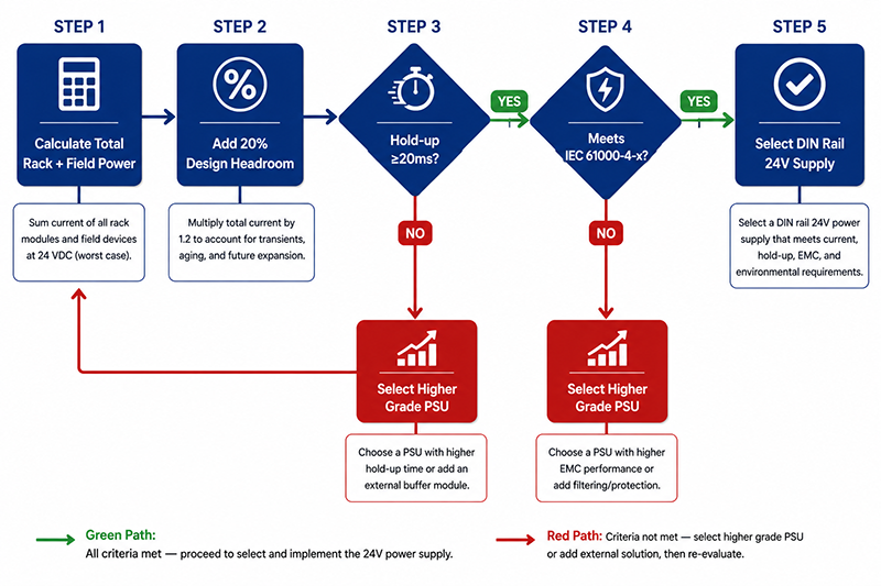
Step 1 — Calculate total power demand
- Sum: CPU module + all I/O modules + communication modules + field power
- Add 20% margin for future expansion
- Account for startup surge (1.5× rated for 1–5 seconds)
Step 2 — Determine hold-up time requirement
- General machine control: ≥10ms
- Process control: ≥20ms + DC-UPS
- Safety-critical: ≥20ms + monitored DC-UPS
Step 3 — Verify noise and immunity specifications
- Output ripple: <50mV for digital-only, <20mV for analog systems
- Input transient immunity: IEC 61000-4-4 (2kV) and IEC 61000-4-5 (1kV)
- Isolation: ≥3000VAC input-to-output
Step 4 — Match form factor and mounting
- DIN rail TS35
- Width within cabinet space budget
- Ambient temperature rating exceeding worst-case cabinet temperature
Step 5 — Verify certifications
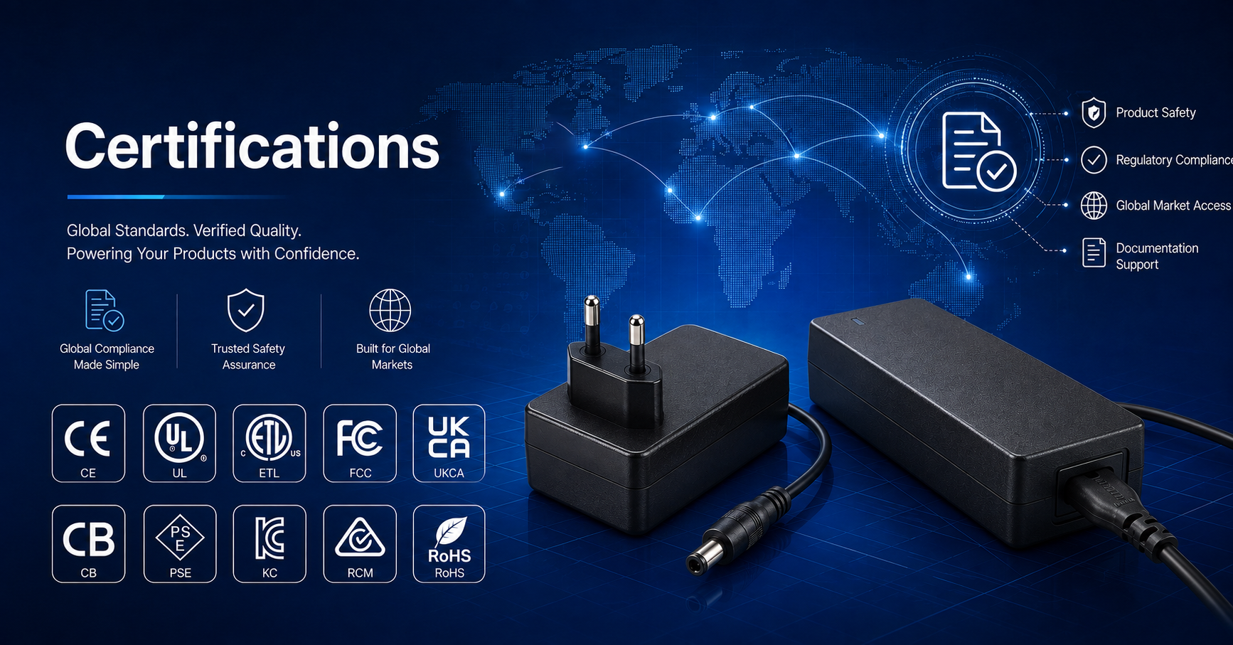
- CE (EU), UL/ETL (US), CCC (China), or applicable per target market
- Certifications available depending on model, application and target market
Why This Matters
- The cost of specifying an undersized power supply is not the replacement cost — it is the production downtime, troubleshooting hours, and potential equipment damage caused by intermittent PLC failures.
- A well-specified PLC power supply with 20% headroom, 20ms hold-up time, and low output ripple costs 30–50% more than a basic industrial supply — this premium is typically recovered within the first year of operation through reduced field failures.
- Certifications available depending on model, application and target market. Verify that the power supply carries the certifications required for your equipment’s target markets.
What OEMs Should Do Now
- Create a power supply specification template for your PLC platform that includes: voltage, current (with 20% margin), hold-up time, ripple, immunity levels, and certifications.
- Include power supply specifications in your PLC cabinet design review checklist — this is the most commonly overlooked item in control panel design.
- For multi-cabinet systems, standardize on one or two power supply models across all cabinets to simplify spares management and reduce qualification costs.
CONCLUSION
PLC power supply selection requires systematic attention to voltage and current per module, hold-up time tailored to the application criticality, noise immunity for the industrial environment, DIN rail mechanical compatibility, and certification for target markets. A PLC system with a properly specified power supply — 20% headroom, adequate hold-up time, and verified noise immunity — will deliver significantly higher field reliability than one where the power supply was an afterthought.
Certifications available depending on model, application and target market.
Frequently Asked Questions
How much headroom should a PLC power supply have?
Allow for startup transients and planned expansion rather than sizing at the arithmetic sum of module ratings. Adding margin at the specification stage is cheaper than discovering the limit once the panel is built.
How is hold-up time decided for a PLC system?
From what the system must do during a mains disturbance. A controlled shutdown, a ride-through of a short dip and an uninterrupted process are three different requirements, and each implies a different amount of stored energy.
What does noise immunity mean for a PLC supply?
It describes how the supply and the system behave when interference arrives — through the mains, through I/O wiring, or radiated. Immunity is a system property: layout, grounding and cable separation contribute as much as the supply.
Does a PLC supply have to be DIN rail mounted?
DIN rail is common because of how control panels are built and serviced, but it is an installation choice rather than a requirement. What matters is retention, thermal path and service access.
How do I confirm certification for a PLC power supply?
Ask for the documentation that names the model and configuration, and confirm the standard and the market it covers. Certification is available by model and depends on the model and the target market.
Related Resources
🔌 Related Products
🏭 Related Applications
Industrial Control Power Solutions
Power solutions for PLC, CNC, servo and automation equipment
📖 Related Guides
✅ Related Certifications
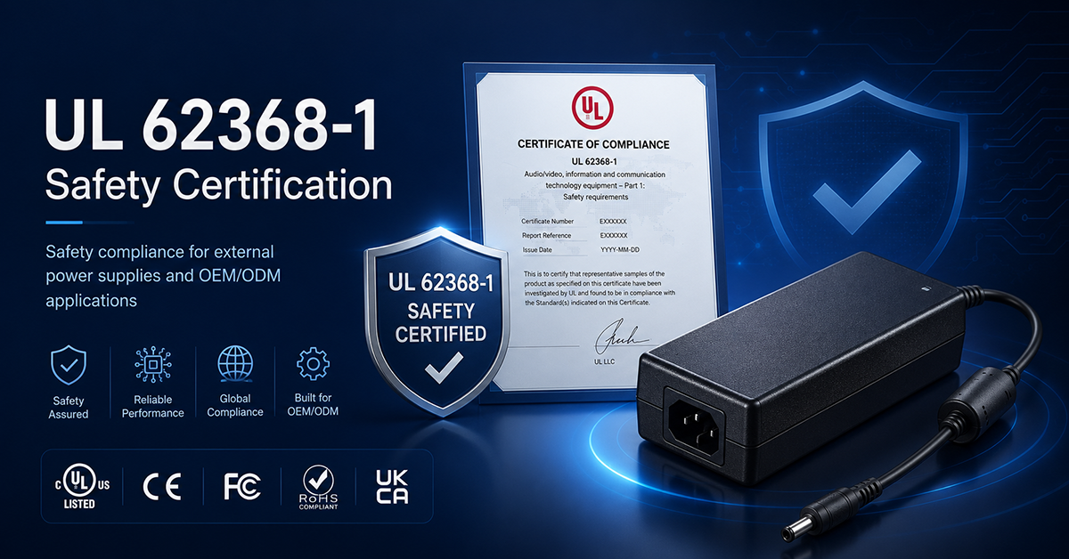
UL 62368-1 Safety Certification
Safety standard covering connector creepage/clearance, temperature rise, and strain relief requirements for IT/AV equipment power adapters.