
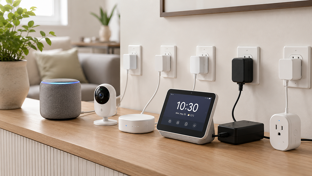
Smart home and IoT devices present a unique set of power supply requirements that distinguish them from traditional consumer electronics. Many smart home devices operate 24 hours a day, seven days a week, drawing power continuously even when the active function (lighting, audio, sensing) is idle. The power supply must deliver reliable power for always-on operation while meeting increasingly strict standby power regulations. Form factor constraints—compact enclosures, wall-mount designs, and aesthetic considerations—further influence adapter selection.
This guide covers the power supply considerations for smart home and IoT device OEMs: standby power regulations, always-on reliability requirements, voltage and current requirements by device type, form factor selection, and certification pathways.
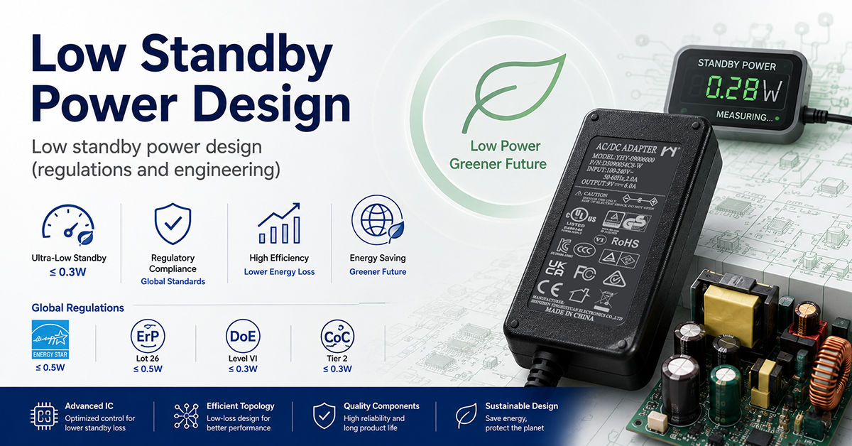
Standby Power Regulations and Low-Power Design
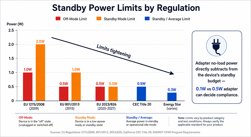
Smart home devices that remain connected to AC power 24/7 are subject to standby power regulations in many markets. These regulations limit the power a device may consume when not performing its primary function.
Key Standby Power Regulations:
| Market | Regulation | Standby Limit | Scope |
|---|---|---|---|
| EU | EU 1275/2008 (amended by 801/2013) | ≤1.0W (off mode), ≤2.0W (standby) | Household and office equipment with AC mains connection |
| EU | EU 2023/826 (Ecodesign standby) | ≤0.5W (off), ≤0.5–1.0W (standby, network-dependent) | Updated limits phased in from 2025 |
| USA | Energy Star | Varies by product category | Voluntary program; products meeting limits qualify for Energy Star mark |
| USA | CEC Title 20 | ≤0.5W (standby for external power supplies) | External power supplies sold in California |
| Global | IEC 62301 | Measurement standard | Defines how standby power is measured |
Design Strategies for Low Standby Power:
| Strategy | Description | Typical Standby Saving |
|---|---|---|
| Adapter with low no-load power | Select adapter with <0.1W no-load consumption | 0.1–0.5W vs standard adapter 0.3–1.0W |
| Load disconnect switch | Disconnect non-essential circuits when device is idle | 0.5–2W depending on circuit |
| Efficient DC-DC conversion | Use high-efficiency regulator for always-on circuits | 10–30% improvement in quiescent current |
| Sleep mode controller | Low-power MCU monitors for wake events | Reduces main processor power from 100mW+ to <1mW |
| Integrated PMIC | Power management IC coordinates power states | System-level optimization |
The adapter’s no-load power consumption contributes to the device’s standby power total. An adapter with 0.1W no-load consumption allows more of the standby budget for the device’s internal circuits than an adapter with 0.5W no-load consumption.
Why This Matters
- EU standby regulations are tightening from 2025 (EU 2023/826), reducing standby limits from 1.0–2.0W to 0.5–1.0W. Devices not meeting these limits cannot be sold in the EU market.
- The adapter’s no-load power consumption directly subtracts from the device’s available standby power budget. A 0.1W versus 0.5W adapter difference can determine whether the device meets a 0.5W standby limit.
- Standby power is measured at the AC input of the complete device (adapter + product). Both the adapter’s no-load consumption and the device’s idle consumption contribute.
What OEMs Should Do Now
- Determine the standby power regulations applicable to your device in each target market. Verify the applicable limits and effective dates.
- Select adapters with low no-load power consumption (0.1W or less where available) to maximize the standby budget for the device’s internal circuits.
- Design the device’s power management architecture to enter low-power states when the primary function is not active. Include a wake-on-event mechanism that does not require continuous full-power operation.
Power Requirements by Smart Home Device Type
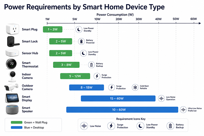
Smart home devices span a wide range of power requirements. The following table shows common ranges as illustrative guidance, not fixed specifications.
| Device Type | Typical Power Range | Common Voltages | Form Factor | Critical Requirements |
|---|---|---|---|---|
| Smart speaker / voice assistant | 10–60W | 12V, 24V | Desktop or wall plug | Low noise for microphone array; transient response for audio amplification |
| Smart display | 15–40W | 12V, 24V | Desktop | Clean power for display and audio; consistent regulation |
| IP camera (indoor) | 5–12W | 5V, 12V, PoE | Wall plug | Reliable power for continuous recording; surge protection for outdoor units |
| IP camera (outdoor) | 8–18W | 12V, 24V, PoE+ | Desktop or PoE | Surge protection; cold-start; IP-rated enclosure |
| Smart sensor hub | 2–5W | 5V, 12V | Wall plug | Low standby; reliable always-on operation |
| Smart thermostat | 3–8W | 5V, 12V, 24VAC | Wall mount (hardwired) | Low power for battery backup compatibility |
| Smart lock | 2–5W (peak) | 3–6V (battery), 5V (USB) | Battery + backup | Peak current for motor drive; low quiescent for battery life |
| Smart plug / switch | 1–3W (device only) | 5V, 12V | Internal PSU or wall plug | Compact size; meets safety standards for built-in PSU |
| Connected camera / baby monitor | 3–10W | 5V, 12V | Wall plug or battery | Low noise for video; consistent supply |
Power Budget Considerations:
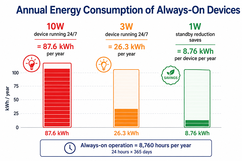
For always-on devices, the total energy consumed over a year is relevant for both operating cost and regulatory compliance:
- A 10W device running 24/7 consumes 87.6 kWh annually
- A 3W device running 24/7 consumes 26.3 kWh annually
- A 1W standby reduction saves 8.76 kWh per device per year
Why This Matters
- Smart speakers and displays with audio playback require better power quality than pure sensor devices. The amplifier stage and microphone array need clean, stable voltage.
- Outdoor cameras and sensors require surge protection and cold-start capability that indoor devices do not.
- Battery-backup-compatible devices (thermostats, locks) need low quiescent current from the adapter to avoid draining backup batteries.
What OEMs Should Do Now
- Create a power budget that includes active mode, idle mode, and standby mode power consumption. Design the device to enter lower power states automatically.
- Select the adapter voltage to minimize conversion losses. A 12V adapter feeding a 3.3V regulator is less efficient than a 5V adapter if the primary load is 3.3V.
- For outdoor smart home devices, include surge protection and cold-start requirements in the adapter specification.
Always-On Reliability Considerations
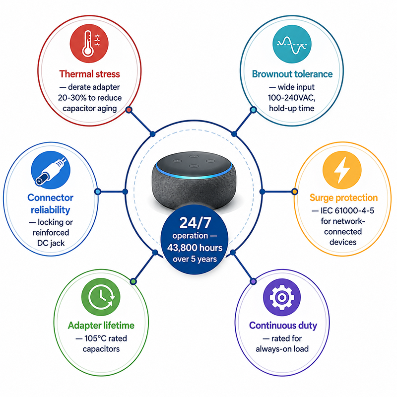
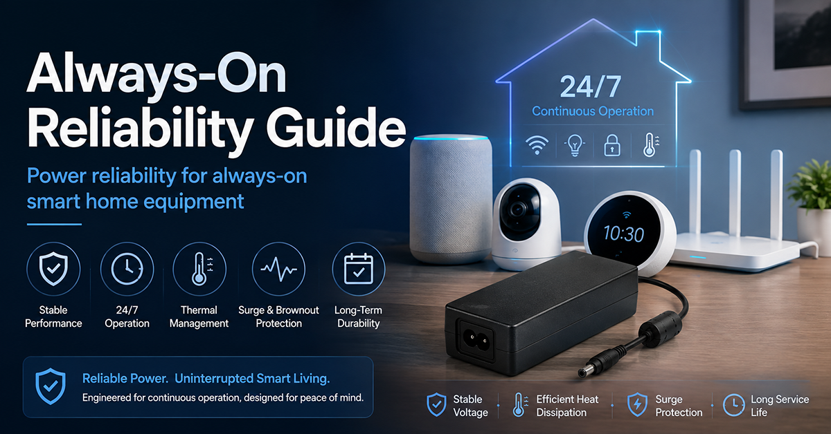
Smart home devices that operate 24/7 place different reliability demands on the power supply compared to devices used intermittently.
| Reliability Factor | Consideration | Design Approach |
|---|---|---|
| Continuous operation | Adapter runs 8,760 hours/year vs ~1,000 for typical consumer device | Select adapter with appropriate capacitor temperature rating and lifetime |
| Thermal stress | Continuous operation at elevated temperature accelerates capacitor aging | Derate adapter by 20–30% to reduce operating temperature |
| Brownout tolerance | AC mains voltage sags affect always-on devices | Specify adapter with wide input range (100–240VAC) and hold-up time |
| Surge protection | Outdoor and network-connected devices exposed to surges | Specify adapter with appropriate surge immunity (IEC 61000-4-5) |
| Connector reliability | Continuous connection with mechanical stress | Locking connector or reinforced DC jack |
| Lifetime | Adapter may be expected to last the device’s service life (3–10+ years) | Verify adapter capacitor lifetime at expected operating temperature |
Reliability Indicators:
Adapter lifetime is primarily determined by electrolytic capacitor lifetime. MTBF data may be available depending on model and calculation methodology. MTBF is a statistical projection, not a guarantee of service life. The operating-temperature range and capacitor quality are model-specific and should be verified from the applicable datasheet.
Why This Matters
- A smart home device expected to operate 24/7 for 5 years accumulates 43,800 operating hours. The adapter’s expected lifetime at the operating temperature should exceed this.
- Adapter derating is a low-cost reliability improvement. An adapter running at 70% of its rated load runs cooler, with lower capacitor stress and longer expected lifetime.
- Brownout tolerance is important for always-on devices. A 10% AC mains sag that an intermittently used device tolerates may reset an always-on device, causing it to lose network connection and require reconnection.
What OEMs Should Do Now
- Select adapters with 105°C-rated capacitors for always-on smart home devices. Verify the expected lifetime at the operating temperature from the manufacturer’s data.
- Specify adapters rated for at least 120% of the calculated maximum continuous power to provide thermal derating margin.
- Test the complete device (adapter + product) under brownout conditions (90VAC input, full load) to verify stable operation.
Form Factor and Connector Considerations
Smart home device form factors often constrain adapter choice. Wall-mount devices, compact enclosures, and aesthetic requirements influence form factor decisions.
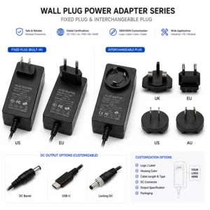
Wall Plug vs Desktop Adapter:
| Factor | Wall Plug | Desktop |
|---|---|---|
| Form factor | Compact, no cable to device | Larger, requires AC cord |
| Best for | Low-power devices <30W: sensors, cameras, plugs | Higher-power devices >30W: speakers, displays |
| Aesthetic | Adapter hidden behind/under device | Adapter visible on surface or concealed |
| Mechanical | Adapter weight supported by outlet | Adapter sits on surface, no outlet strain |
| Thermal | Heat from adapter near wall outlet | Adapter can be placed in ventilated area |
Connector Types:
- Barrel connector (2.1mm, 2.5mm): Common for smart home devices up to 36W. Polarity (center-positive vs center-negative) must be specified on the device label.
- USB-C PD: Increasingly common for consumer smart home devices. Supports voltage negotiation (5V, 9V, 12V, 15V, 20V) and can power devices up to 100W. USB-C PD may be considered for new designs where the voltage and power requirements, user experience, interoperability, and certification strategy support it.
- USB-A: Common for low-power devices (up to 10W at 5V). Limited to 2.4A typical.
- Proprietary connector: Used for devices requiring a specific mechanical or electrical interface.
Why This Matters
- Wall plug adapters for devices above 30W are uncommon due to mechanical stress on the outlet. Desktop adapters are generally preferred as power requirements increase.
- USB-C PD simplifies user experience because a single adapter can power devices with different voltage requirements through voltage negotiation.
- The connector type should be selected to match the device’s power requirement, mechanical constraints, and the target market’s user expectations.
What OEMs Should Do Now
- Evaluate the device’s power requirement, mounting location, and user interaction to determine the appropriate adapter form factor.
- Consider USB-C PD for new consumer-facing device designs where the voltage and power requirements, user experience, interoperability, and certification strategy support it.
- Specify the connector type, polarity, and voltage rating clearly on the device label and in the product documentation.
Q: What is the best power adapter voltage for a smart home device with 3.3V and 1.8V internal rails?
A: A 5V adapter is a common choice because the 5V to 3.3V conversion has reasonable efficiency with an LDO (1.7V dropout, 66% efficiency) or a small DC-DC converter. A 12V adapter would require a larger voltage drop, increasing conversion losses unless a DC-DC converter is used. The optimal voltage depends on the total power requirement and the efficiency of the onboard regulation stage.
Q: Can smart home devices use USB power adapters for their main power?
A: Yes, many low-power smart home devices (sensors, cameras, hubs) use standard USB-A or USB-C power adapters. This simplifies certification and user experience because the user may already have a compatible adapter. The device must specify the minimum current rating required. For higher-power devices (>10W), a dedicated adapter is typically necessary.
Q: How low should standby power be for a smart home device meeting EU regulations?
A: EU 2023/826 sets standby limits of 0.5W (off mode) and 0.5–1.0W (standby with network connection) for most devices. Designing for ≤0.5W standby is a practical target for devices sold in EU markets, accounting for both the adapter’s no-load consumption and the device’s idle power draw.
CONCLUSION
Smart home and IoT device power supply selection requires attention to standby power regulations, always-on reliability, device-specific voltage and current requirements, and form factor constraints. The key considerations are: selecting an adapter with low no-load power consumption to meet standby regulations, choosing adapter voltage to minimize conversion losses, derating the adapter for continuous operation reliability, and selecting the appropriate form factor and connector for the device’s installation environment.
Related Resources
🔌 Related Products
📖 Related Guides
Low Standby Power Design
Low standby power design (regulations and engineering)
Read Guide →
🏭 Related Applications
✅ Related Certifications
UL 62368-1 Safety Certification
Safety standard covering connector creepage/clearance, temperature rise, and strain relief requirements for IT/AV equipment power adapters.