
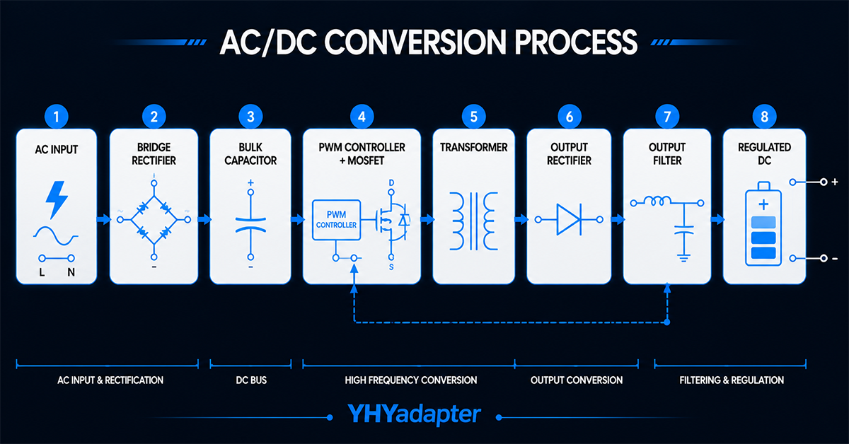
Why AC/DC Conversion Matters
Every electronic device that plugs into a wall outlet needs AC/DC conversion. The mains power delivered to homes and factories is alternating current (AC) at 100–240 V and 50–60 Hz, but virtually every electronic circuit—from a microcontroller to a medical monitor to an LED panel—requires direct current (DC) at a much lower voltage.
The power supply that performs this conversion is one of the most critical components in any electronic product. How well it converts AC to DC determines:
- Safety — Proper isolation between mains and low-voltage circuits prevents electric shock
- Reliability — Clean, regulated DC power prevents erratic behavior and premature component failure
- Efficiency — A conversion that wastes less energy means less heat, smaller enclosures, and lower operating costs
- Certification — The quality of the conversion chain directly affects EMI, harmonics, and safety compliance
This guide walks through each stage of the AC/DC conversion process in a typical external power adapter, from incoming mains voltage to the regulated DC output your equipment depends on.
🛠️ Engineering Tip: Understanding the basic conversion stages helps you ask better questions when reviewing power supply datasheets. When a spec says “efficiency > 88%” or “ripple & noise < 100 mVpp”, you’ll know exactly where those numbers come from and how they affect your application.
Section 1: AC vs DC — The Fundamental Difference
Alternating Current (AC)
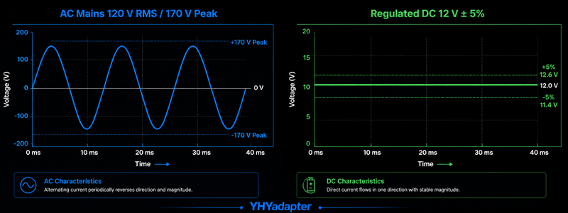
AC voltage changes polarity periodically. In a 60 Hz system, the voltage cycles from positive to negative and back 60 times per second. In a 50 Hz system, 50 times per second.
The mains voltage you see quoted (e.g., 120 VAC or 230 VAC) is the RMS (root mean square) value — the equivalent DC voltage that would deliver the same power to a resistive load. The actual peak voltage is approximately 1.414× the RMS value:
| Nominal Mains | RMS Voltage | Peak Voltage | Peak-to-Peak |
|---|---|---|---|
| 120 VAC (North America) | 120 V | 170 V | 340 V |
| 230 VAC (Europe/Asia) | 230 V | 325 V | 650 V |
| 100 VAC (Japan) | 100 V | 141 V | 282 V |
| 264 VAC (global max) | 264 V | 373 V | 746 V |
Direct Current (DC)
DC voltage maintains a constant polarity. Most electronic circuits require DC with minimal variation — typically within ±5% of the nominal voltage. Excessive variation (ripple) can cause logic errors in digital circuits, audio hum in analog circuits, or erratic motor behavior.
Key difference for power supply design: AC can be transformed (voltage stepped up or down) using a simple transformer. DC cannot be transformed directly — it must first be converted back to AC (inverted), transformed, then rectified again. This is why switch-mode power supplies use high-frequency AC internally even though the input and output are AC and DC respectively.
Section 2: The AC/DC Conversion Block Diagram
A modern switch-mode power supply (SMPS) follows this sequence:
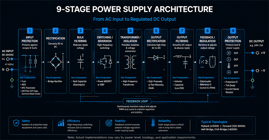
Figure 1: AC/DC Conversion Stages — Each block transforms the electrical energy toward the final regulated DC output.
| Stage | Function | Key Component(s) |
|---|---|---|
| 1. Input Protection | Surge protection, EMI filtering | Fuse, MOV, common-mode choke, X/Y capacitors |
| 2. Rectification | Converts AC to pulsating DC | Bridge rectifier diode |
| 3. Bulk Filtering | Smooths pulsating DC into rough DC | Large electrolytic capacitor(s) |
| 4. Switching / Inversion | Converts DC back to high-frequency AC | MOSFET(s), PWM controller, transformer |
| 5. Transformer / Isolation | Steps voltage down, provides isolation | High-frequency transformer |
| 6. Output Rectification | Converts high-frequency AC to DC | Schottky diodes or synchronous MOSFETs |
| 7. Output Filtering | Removes switching ripple | Electrolytic + ceramic capacitors, output inductor |
| 8. Feedback / Regulation | Compares output to reference, adjusts switching | Optocoupler, voltage reference, error amplifier |
| 9. Output Protection | Overvoltage, overcurrent, short-circuit protection | Crowbar circuit, current sense resistor, latch-off IC |
The next sections cover the four most critical stages in detail.
Section 3: Stage 1 — Rectification
What Happens
The bridge rectifier converts AC voltage into pulsating DC. It does this using four diodes arranged in a bridge configuration. At any point in the AC cycle, two diodes conduct — one pair during the positive half-cycle and the other pair during the negative half-cycle — ensuring the output always has the same polarity.
Before and After
| Measurement | AC Input | Rectified Output |
|---|---|---|
| Waveform shape | Sine wave | Full-wave rectified sine (all peaks upward) |
| Frequency | 50/60 Hz | 100/120 Hz |
| Voltage | 100–240 VAC RMS | ~141–373 V peak (minus ~1.4 V diode drop) |
What to Watch For
- Diode drop: Each conducting path has two diodes, so the total forward voltage drop is ~1.0–1.4 V. At high currents this generates significant heat.
- Inrush current: When power is first applied, the empty bulk capacitors look like a short circuit. Inrush can exceed 50 A peak — managed by an NTC thermistor or resistor relay circuit.
- Reverse recovery: Diode switching loss becomes significant at high frequencies. Schottky diodes (with no reverse recovery) are preferred in the output stage.
🛠️ Engineering Tip: If you see a datasheet specify “universal input 90–264 VAC,” that 90 V minimum accounts for the rectified voltage dropping below the bulk capacitor voltage during brownout conditions, plus the diode drop. The actual rectified peak at 90 VAC is approximately 90 × 1.414 − 1.4 = 126 V.
Section 4: Stage 2 — Filtering
What Happens
After rectification, the voltage is a series of peaks reaching zero between each cycle. The bulk capacitor stores energy during the peaks and releases it during the valleys, producing a smoother DC voltage with a characteristic “ripple” at twice the mains frequency (100 or 120 Hz).
Ripple Voltage
The ripple voltage depends on three factors:
- Capacitance (C): Larger capacitance = less ripple
- Load current (I): Higher current = more ripple
- AC line frequency (f): 60 Hz systems have less ripple than 50 Hz (shorter time between charging peaks)
Approximate ripple formula: V_ripple(pp) = I_load / (f × C)
Example: A 120 W supply (10 A at 12 V) with a 220 µF bulk capacitor at 60 Hz:
V_ripple = 10 / (120 × 220×10⁻⁶) = 10 / 0.0264 = 379 Vpp — clearly impossible. This is why offline supplies (running directly from mains) use much larger bulk capacitors (100–470 µF at 400–450 V) and why the intermediate DC bus has ripple of 10–40 Vpp that must be regulated by the downstream switching stage.
Hold-Up Time
The bulk capacitor also provides hold-up time — the duration the supply can maintain output after input power is lost. A typical specification is 16–20 ms (one mains cycle). Larger bulk capacitance extends hold-up time but increases inrush and cost.
Section 5: Stage 3 — Regulation
What Happens
Regulation is the most sophisticated stage in an AC/DC converter. The unregulated DC bus (varying between ~120 V and ~373 V depending on input voltage and load) is switched at high frequency—typically 65 kHz to 200 kHz—through a transformer to produce a regulated output.
How Regulation Works (Feedback Loop)
- The PWM controller drives the MOSFET(s) at a fixed frequency
- The MOSFET switches the DC bus voltage across the transformer primary
- The transformer secondary voltage is rectified and filtered
- The output voltage is sampled by a feedback circuit (usually via an optocoupler for isolation)
- The sampled voltage is compared to an internal reference
- The PWM controller adjusts the duty cycle (on-time vs off-time ratio) to maintain the output voltage
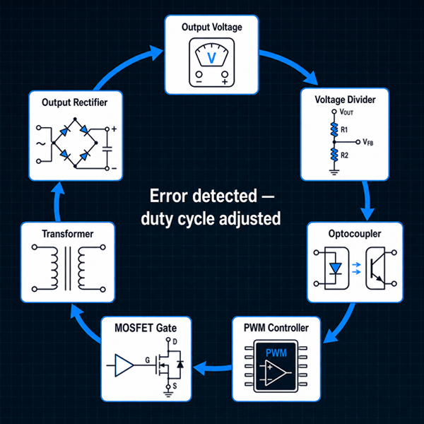
Result: The output stays at 12 V (or 24 V, 48 V, etc.) regardless of whether the input is 100 V or 240 V, and regardless of whether the load is 10% or 100% of rated current — within the specified regulation band (±1–5% typical).
Switching Frequencies
| Frequency | Advantages | Trade-offs |
|---|---|---|
| 65–75 kHz | Low switching loss, good efficiency | Larger transformer |
| 100–150 kHz | Smaller transformer, popular for 100–300 W | Moderate switching loss |
| 200–500 kHz | Very small transformer, GaN enabled | Higher switching loss, EMI challenges |
Section 6: Stage 4 — Isolation
What Happens
Isolation is a safety-critical function that separates the high-voltage primary side (connected to mains) from the low-voltage secondary side (connected to user-accessible equipment). The transformer provides galvanic isolation: primary and secondary windings are physically separated, with no electrical DC path between them.
Why Isolation Matters
- User safety: Without isolation, a component failure could put mains voltage on the output cable. Reinforced isolation (per IEC 62368-1 or IEC 60601-1) ensures safety even under single-fault conditions.
- Noise immunity: The isolation barrier prevents ground loops and reduces conducted noise between mains and the sensitive electronics.
- Certification: Medical equipment requires 2× MOPP (Means of Patient Protection) — two independent insulation layers or reinforced insulation between primary and secondary.
Key Isolation Parameters
| Parameter | Typical Value | Purpose |
|---|---|---|
| Creepage distance | ≥ 6.4 mm (basic), ≥ 8 mm (reinforced) at 250 VAC | Physical surface distance |
| Clearance | ≥ 4 mm (basic), ≥ 6 mm (reinforced) at 250 VAC | Air gap distance |
| Dielectric strength (Hi‑Pot) | 1500–4000 VAC for 60 s | Proves insulation integrity |
| Leakage current | < 0.5 mA (IT), < 0.1 mA (medical BF) | Current leakage through isolation capacitance |
🛠️ Engineering Tip: When you see an adapter advertised as “medical grade,” one of the key differences is the isolation transformer. Medical-grade transformers use triple-insulated wire on the secondary, wider creepage distances, and lower inter-winding capacitance — all of which reduce leakage current to the safety levels required by IEC 60601-1.
Need help specifying the right AC/DC conversion topology for your project?
Our application engineering team can guide your selection.
Section 7: Efficiency and Power Loss
Where Energy Is Lost
No AC/DC conversion is 100% efficient. Energy is dissipated as heat in several stages:
| Loss Source | Typical % of Total Loss | How to Minimize |
|---|---|---|
| MOSFET switching losses | 25–35% | Lower frequency, faster switching devices (GaN, SiC) |
| MOSFET conduction losses | 20–30% | Lower Rds(on) MOSFETs |
| Transformer core + copper | 15–25% | Better core material, Litz wire, optimized design |
| Diode rectifier losses | 10–20% | Synchronous rectification (MOSFETs instead of diodes) |
| Control + auxiliary circuits | 5–10% | Low-power standby ICs |
| Input filter + wiring | 1–3% | Low-resistance components |
Typical Efficiency Levels
| Power Level | Standard Efficiency | High Efficiency (+ premium) |
|---|---|---|
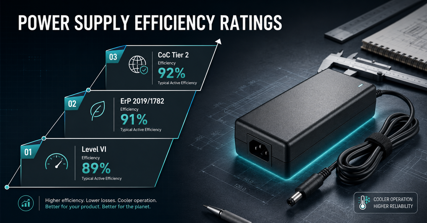
| < 30 W | 75–82% | 83–88% (DoE Level VI / CoC Tier 2) |
| 30–150 W | 82–88% | 88–92% |
| 150–600 W | 85–90% | 90–94% |
| > 600 W | 88–92% | 93–96% |
The Efficiency vs Size Trade-Off
Increasing efficiency usually requires larger components (better heatsinking, lower-resistance magnetics, larger switching devices) or more expensive materials (GaN FETs, planar transformers, synchronous rectification). For a given power level, a 90% efficient adapter will be physically smaller than an 88% efficient one because less heat needs to be dissipated — but cost per watt typically increases by 15–25% per efficiency point above 90%.
Section 8: Common AC/DC Topologies at a Glance
Different power levels and applications use different switching topologies. Each has trade-offs in cost, efficiency, complexity, and noise.
| Topology | Power Range | Efficiency | Cost | Typical Use |
|---|---|---|---|---|
| Flyback | 5–150 W | Medium | Low | Most wall-mount and small desktop adapters |
| LLC Resonant | 100–600 W | High | Medium | High-efficiency desktop, medical, industrial |
| Half-Bridge | 150–500 W | Medium | Medium | Mid-power industrial and audio |
| Full-Bridge | 500 W+ | High | High | High-power industrial, server, EV charging |
| Push-Pull | 100–500 W | Medium | Medium | Battery chargers, telecom |
Flyback is by far the most common topology for external power adapters up to 150 W. It uses the fewest components and is well-understood by manufacturers worldwide. Above 150 W, LLC resonant and half-bridge topologies become more efficient.
Frequently Asked Questions
1. What is the difference between a linear power supply and a switch-mode power supply?
A linear power supply uses a heavy 50/60 Hz transformer to step down voltage, then rectifies and regulates it. It is simpler, quieter (no switching noise), but large, heavy, and inefficient (typically 40–60%). A switch-mode supply (SMPS) uses a high-frequency switching stage, is much smaller and lighter, and achieves 80–94% efficiency. Over 95% of modern external power adapters are switch-mode.
2. What is “no-load power consumption”?
No-load power (or standby power) is the power the adapter consumes when plugged into the wall but not connected to any device. Modern efficiency regulations (DoE Level VI, CoC Tier 2) limit no-load power to < 0.1 W for adapters rated below 250 W. Older adapters can draw 0.3–0.5 W or more at no load.
3. Why do some adapters get warm even when not powering a device?
Even at no load, the adapter’s control circuits, startup resistor, and leakage through the transformer and snubber circuits consume a small amount of power. A Level VI compliant adapter at no load consumes < 0.1 W, which translates to negligible heat — just barely perceptible to the touch. If an adapter is noticeably warm with no load connected, it may be an older, less efficient design.
4. What does “universal input” mean?
“Universal input” means the power supply automatically accepts any mains voltage from 90–264 VAC at 47–63 Hz without manual switching. This is standard on modern switch-mode power supplies and is essential for OEM products sold globally — one SKU works worldwide.
5. Can I use a 60 Hz rated adapter on a 50 Hz mains supply?
Yes, and vice versa. All modern switch-mode power supplies with universal input (90–264 VAC, 47–63 Hz) operate at both 50 Hz and 60 Hz. The only difference is that bulk capacitor ripple is slightly higher at 50 Hz because the charging interval is longer. This is factored into the design.
6. What is the purpose of the optocoupler in an AC/DC converter?
The optocoupler (or opto-isolator) provides feedback from the secondary (low-voltage) side to the primary (mains-voltage) side while maintaining galvanic isolation. It contains an LED and a phototransistor in the same package. As the output voltage varies, the LED brightness changes, which the phototransistor detects and relays to the PWM controller. This feedback loop is what enables the tight voltage regulation (±1–5%) that modern electronics require.
Key Takeaways
- AC/DC conversion is a multi-stage process. Each stage — rectification, filtering, regulation, isolation — has specific components and trade-offs. Understanding the chain helps you evaluate power supply quality.
- The bulk capacitor is the heart of the input stage. It determines ripple voltage and hold-up time. Larger capacitance improves ripple but increases inrush and cost.
- Regulation is achieved through a closed feedback loop. The PWM controller continuously adjusts the switch duty cycle to maintain the output voltage regardless of input voltage or load variations.
- Isolation is a safety-critical function. Galvanic isolation between primary and secondary prevents mains voltage from reaching user-accessible circuits. Creepage, clearance, and Hi-Pot testing verify isolation integrity.
- Efficiency losses are distributed across multiple stages. MOSFET switching losses, transformer losses, and rectifier losses are the three largest contributors. Higher efficiency requires better components and often higher cost.
- Flyback is the dominant topology for external adapters. Below 150 W, its simplicity and low cost make it the industry standard. Above 150 W, LLC and half-bridge topologies become more efficient.
Conclusion: From Mains to Clean DC
Every time you plug in a power adapter, a sophisticated conversion chain transforms dangerous, high-voltage AC mains into safe, clean, regulated DC power. Understanding this chain — from the bridge rectifier’s four diodes to the PWM controller’s nanosecond timing to the optocoupler’s feedback loop — gives you a deeper appreciation for the engineering inside that black brick.
For OEM engineers, this knowledge translates directly to better specification decisions. When you understand why a 450 V bulk capacitor is preferable to a 400 V type, or why 8 mm creepage matters for reinforced insulation, or how flyback topology limits maximum power, you can evaluate power supply proposals with far greater confidence.
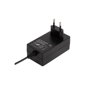
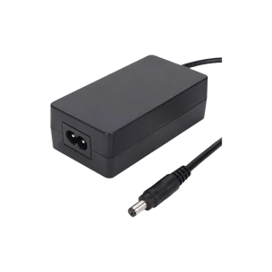
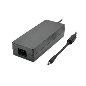
YHYadapter’s power adapter range — from compact wall-mount units to high-efficiency desktop adapters to custom open frame designs — incorporates all the stages described in this guide with careful attention to component selection, thermal management, and safety compliance.
Need help understanding the AC/DC conversion requirements for your product?
Our engineering team can explain the trade-offs between topologies, help you select the right efficiency tier, and provide detailed specifications tailored to your application.
Related Resources
🔌 Related Products
📖 Related Guides
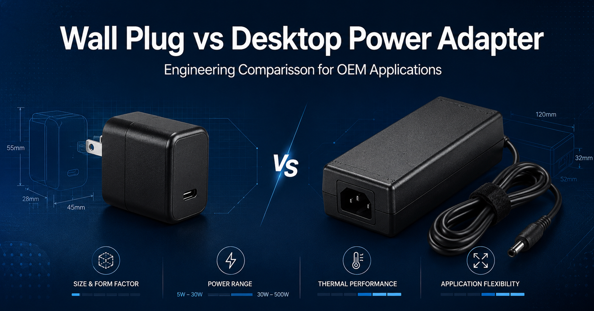
Wall Plug vs Desktop Power Adapter
Engineering comparison of wall plug vs desktop form factors
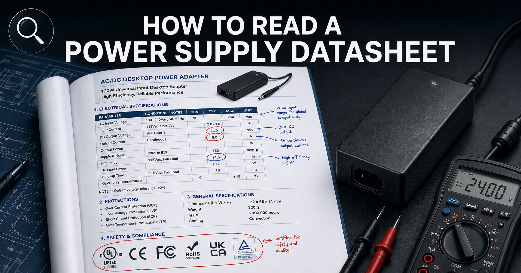
How to Read a Power Supply Datasheet
Learn how to evaluate connector specifications in a datasheet — current ratings, derating curves, certification verification.
🏭 Related Applications
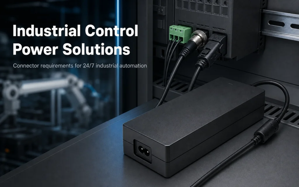
Industrial Control Power Solutions
Desktop power supplies designed for PLC panels, CNC controllers, and industrial automation systems.
✅ Related Certifications
UL 62368-1 Safety Certification
Safety standard covering connector creepage/clearance, temperature rise, and strain relief requirements for IT/AV equipment power adapters.