

In OEM power supply design, the DC output connector is often treated as an afterthought—until it becomes the source of field failures, compatibility complaints, or certification delays. A connector that seems adequate on paper can introduce voltage drop, overheat under continuous load, or fail mechanically in a vibrating environment.
Connector selection directly affects:
- Safety — Undersized contacts can overheat, melt housings, or start fires under sustained load.
- Voltage drop — High-resistance contacts or thin cable gauges reduce the voltage reaching the load, potentially causing system brownouts or erratic behavior.
- Reliability — Connectors with insufficient mating cycles or poor strain relief fail prematurely in field-deployed equipment.
- User experience — Wrong polarity, incompatible plug sizes, or difficult mating frustrates end users and drives returns.
- Certification — Connectors used in medical, industrial, or outdoor applications must meet specific safety and environmental standards.
- Field failures — Loose connections cause intermittent faults that are among the hardest to diagnose in the field.
- OEM integration — Connector footprint, cable exit angle, and locking mechanism affect enclosure design and assembly line processes.
This guide provides a comprehensive framework for selecting the right DC power connector for your OEM application. It covers 12 major connector families with their current ratings, locking options, suitable applications, and common pitfalls—concluding with a practical selection matrix and downloadable comparison tool.
Connector Selection Fundamentals
Before diving into specific connector families, it is essential to understand the parameters that govern any DC power connection.
Rated Voltage
The connector’s voltage rating must exceed the maximum output voltage of the power supply. Most DC power connectors are rated for 30–60 VDC, which covers the vast majority of external power adapters (5–48 V). For higher-voltage applications (48–400 VDC), specialized connectors such as Anderson, GX, or terminal blocks with appropriate clearance and creepage distances are required.
Rated Current
This is the most commonly misapplied parameter. A barrel connector’s current rating depends not only on the contact size but also on:
- Contact material — Brass vs phosphor bronze vs beryllium copper
- Contact plating — Tin, nickel, or gold (gold minimizes oxidation and contact resistance)
- Ambient temperature — Connector ratings derate at elevated temperatures
- Continuous vs intermittent load — A connector rated for 5 A peak may not sustain 5 A continuously
- Number of insertions — Contact resistance increases over the connector’s lifetime
🛠️ Engineering Tip: Always use the connector vendor’s derated current rating for continuous load, not the theoretical maximum. A common 5.5×2.5 mm barrel connector at 5 A continuous load in a 50 °C ambient may operate at only 60–70% of its room-temperature rating.
Contact Resistance
Every connection adds resistance. A typical barrel connector has 10–50 mΩ contact resistance. At 5 A, this generates 0.25–1.25 W of heat at the connection point—enough to soften plastic housings in poorly designed connectors.
Watch for the compounding effect: A connector will multiple connections in series, each adding its own resistance and heat.
Cable Gauge and Length
The wire connecting the power supply to the load is part of the connector system. Common gauges for DC power cables:
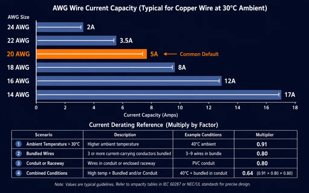
| Cable Gauge | Max Current (chassis wiring) | Typical Use |
|---|---|---|
| 20 AWG | 5 A | Low-power adapters, short cables (< 1 m) |
| 18 AWG | 8 A | Medium-power adapters (up to 60 W) |
| 16 AWG | 12 A | High-power adapters (60–120 W) |
| 14 AWG | 17 A | Very high power (> 120 W), battery systems |
At 5 A through 2 m of 20 AWG cable, voltage drop is approximately 0.4 V—enough to matter in a 5 V system but negligible in a 24 V system.
Polarity
DC connectors must be wired with consistent polarity. The industry standard for barrel connectors is center positive (tip = positive, sleeve = ground), but exceptions exist. Always verify polarity markings on the adapter and the mating device.
Mating Cycles
Connectors are rated for a finite number of insertion/removal cycles:
- Standard barrel: 1,000–5,000 cycles
- Locking connectors: 500–2,000 cycles
- XLR: 1,000–5,000 cycles
- USB-C: 10,000 cycles (rated)
- Anderson: 10,000+ cycles
Locking Mechanism
A locking connector prevents accidental disconnection in vibrating or mobile environments. Options include threaded barrels, snap-lock rings, bayonet couplings, and latch-based connectors.
Strain Relief
Cable strain at the connector entry point is a leading cause of field failure. Proper strain relief—through overmolding, boots, or mechanical clamps—extends connector life by an order of magnitude.
IP / Environmental Protection
For outdoor, washdown, or wet-environment applications, connectors must carry an appropriate IP rating:
- Unrated: Indoor dry locations
- IP54: Splash-resistant, limited dust
- IP65/67: Water-jet resistant, dust-tight
- IP68: Continuous immersion
Connector Keying
Keyed connectors (DIN, XLR, USB-C) prevent incorrect insertion. Non-keyed connectors (barrel, ring terminals) rely on consistent user behavior or mechanical polarization.
Barrel Connectors
Barrel connectors (also called coaxial power connectors or jack plugs) are the most common DC power connector in external power adapters. They consist of a cylindrical male plug that inserts into a matching female jack.
Common Sizes
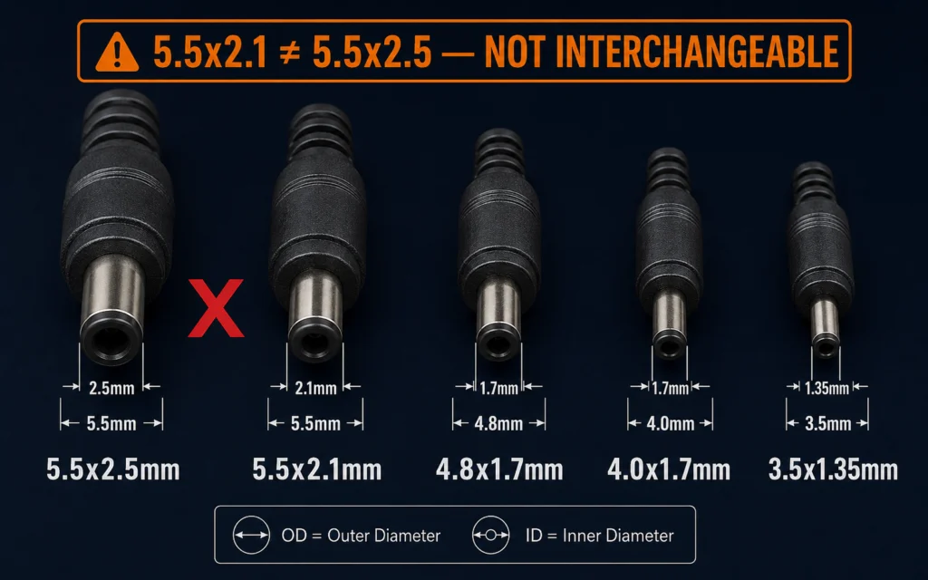
| Size (OD × ID) | Typical Current | Common Use | Notes |
|---|---|---|---|
| 5.5 × 2.5 mm | 3–7 A | Desktop adapters, medical equipment, industrial gear | Most common size for ≥ 36 W adapters. Higher current capacity than 2.1 mm variant. |
| 5.5 × 2.1 mm | 2–5 A | Consumer electronics, wall plug adapters, low-power devices | Older standard, still very common. Lower current than 2.5 mm. |
| 3.5 × 1.35 mm | 1–2.5 A | Portable devices, low-power equipment | Compact size, limited current. |
| 4.0 × 1.7 mm | 1–3 A | Cameras, small peripherals | Mid-range size. |
| 4.8 × 1.7 mm | 2–3 A | Select industrial and telecom devices | Less common. |
Current Limitations
Barrel connectors rely on spring-finger or leaf-spring contacts for electrical connection. This design inherently limits current capacity because:
- Contact area is small (a few mm² at most)
- Spring tension degrades over time, increasing resistance
- Plastic housings soften above 80–100 °C
- No positive locking mechanism exists for standard barrels
🛠️ Engineering Tip: For continuous loads above 5 A at 12 V or higher, consider switching from a standard barrel connector to a locking barrel, XLR, GX, Anderson, or terminal block solution. A 5.5×2.5 mm barrel operated above 5 A continuous will run hot and may fail prematurely.
Polarity
Standard polarity is center positive (tip = V+, sleeve = GND). Reverse polarity is sometimes used but rare in modern equipment. Always verify and specify polarity in your procurement documentation.
5.5×2.1 vs 5.5×2.5 Incompatibility
These sizes share the same outer diameter (5.5 mm) but differ in inner diameter (2.1 mm vs 2.5 mm). A 2.5 mm plug will NOT reliably fit a 2.1 mm jack (the pin is too large). A 2.1 mm plug in a 2.5 mm jack will have a loose connection with poor contact and high resistance.
Critical procurement rule: If your OEM product specification calls for 5.5×2.5 mm, do not accept 5.5×2.1 mm samples. The two are not interchangeable.
Locking DC Connectors
Locking DC connectors add mechanical retention to prevent accidental disconnection in vibration, mobile, or user-handled applications. Three main locking mechanisms exist:
Thread-Locking Barrel Connectors
These use a threaded collar that screws onto a mating threaded jack. The barrel pin and socket remain the same as standard connectors, but the threaded collar provides mechanical retention.
- Current: Same as equivalent barrel connector (2–7 A)
- Typical use: Medical devices, laboratory equipment, portable instruments
- Advantage: Simple, compact, backward-compatible with standard jacks (if threaded collar is removable)
Snap-Lock Connectors
A spring-loaded ring or ball detent engages a groove in the mating connector, providing an audible “click” when fully seated.
- Current: 2–8 A depending on size
- Typical use: Beauty equipment, consumer appliances, handheld devices
- Advantage: Quick disconnect, tactile confirmation of connection
Bayonet-Style Connectors
A push-and-twist mechanism (similar to BNC connectors) provides rapid locking and unlocking.
- Current: 3–15 A depending on size
- Typical use: Industrial equipment, medical systems, field-serviceable devices
- Advantage: Fast connection/disconnection, robust locking
Mini-DIN and DIN Connectors
DIN connectors are circular, multi-pin connectors originally standardized by the German Institute for Standardization (DIN). Mini-DIN is a smaller variant popular in consumer electronics.
Key Features
- Pin count: 3–8 pins (Mini-DIN), 3–13 pins (full DIN)
- Keying: Polarized to prevent incorrect insertion
- Current per pin: Typically 1–2 A (Mini-DIN), 2–5 A (DIN)
- Combined signal + power: One connector for both DC power and control signals
Typical Applications
- Mini-DIN: Audio/video equipment, power adapters with control signaling, laptop docking stations
- DIN: Broadcast equipment, industrial control, medical devices, professional audio
Limitations
- Current per pin is limited—not suitable for high-power single-rail applications
- Full DIN connectors are large and require panel space
- Mini-DIN pins are thin and can bend during rough handling
XLR Power Connectors
XLR connectors (originally designed for audio) are increasingly used for DC power in professional audio, broadcast, medical, and industrial equipment due to their robust locking mechanism and reliable contact design.
Common Configurations
| Pins | Polarity | Typical Use |
|---|---|---|
| 3-pin | Pin 1 = GND, Pin 2 = V+, Pin 3 = V− (or unused) | Audio equipment, medical devices |
| 4-pin | Various pin assignments | Broadcast intercom, professional cameras |
| 5-pin | Various pin assignments | DMX lighting with power, custom OEM |
Advantages
- Positive latching lock — Cannot be pulled out accidentally
- Rugged construction — Metal housing, high mating cycle rating
- Shielded — Good EMC performance for sensitive applications
- Standardized — Widely available from multiple manufacturers (Neutrik, Amphenol, Switchcraft)
Limitations
- Current limited to 6 A per pin (standard XLR) or up to 15 A (power XLR, e.g., Neutrik powerCON)
- Requires panel space for mounting
- Higher cost per connection than barrel connectors
🛠️ Engineering Tip: For OEM audio equipment or medical devices requiring a locking, shielded DC power connection at 3–6 A, a 3-pin XLR with properly assigned power pins is a field-proven solution.
GX / Aviation Connectors
GX connectors (also referred to as aviation connectors, military-style circular connectors) are multi-pin circular connectors with threaded locking. The “GX” designation (e.g., GX12, GX16, GX20) refers to the outer diameter of the connector body in millimeters.
Common Sizes
| Size | OD | Typical Pins | Typical Current per Pin | Common Use |
|---|---|---|---|---|
| GX12 | 12 mm | 2–5 | 3–5 A | Sensors, instrumentation |
| GX16 | 16 mm | 2–7 | 5–10 A | Industrial equipment, power supply outputs |
| GX20 | 20 mm | 3–10 | 7–15 A | Higher-power industrial, battery systems |
Important Clarification
The term “aviation connector” is commonly used commercially to describe GX-type circular connectors with threaded locking. This does NOT imply aerospace certification. True MIL-SPEC or aerospace-grade connectors (such as MIL-DTL-38999 or ARINC) are built to far stricter standards and cost significantly more. GX connectors are industrial-grade circular connectors suitable for factory and commercial equipment, not certified aircraft wiring.
Advantages
- Threaded locking — excellent vibration resistance
- Multiple pin configurations available
- Good current capacity, especially in larger sizes
- IP67 rated options available
Limitations
- Larger panel footprint than barrel connectors
- Assembly requires soldering or crimping each pin
- GX naming convention is not a formal standard—quality varies by manufacturer
Anderson PowerPole Connectors
Anderson PowerPole connectors (also known as SB series) are genderless, housing-based DC connectors designed for high-current applications.
Key Features
- Genderless design: Each half is identical, making it impossible to have a “male” vs “female” connector
- Current rating: 15–50 A depending on housing size (SB15, SB30, SB50, SB120)
- Color coding: Housings available in multiple colors for voltage or circuit identification
- Crimp-only termination: No soldering required; consistent, gas-tight crimp connections
- Rack-and-panel compatible: Allows blind mating in equipment racks
Typical Applications
- Battery charging systems — Forklifts, floor-cleaning machines, UPS
- Energy storage — Solar battery banks, power stations
- Industrial equipment — Rack-mount power, broadcast, emergency vehicles
- Amateur radio / RV / off-grid — High-current DC distribution
Limitations
- Requires proper crimping tooling (do not use generic crimpers)
- Larger than barrel or XLR connectors
- No built-in sealing (IP rating depends on housing)
XT30 / XT60 / XT90 Connectors
XT-series connectors are high-current, bullet-type DC connectors originally developed for RC (radio-controlled) hobby applications and now widely used in battery charging, energy storage, and portable power systems.
| Variant | Rated Current | Typical Wire | Common Use |
|---|---|---|---|
| XT30 | 30 A | 14–16 AWG | Lighter battery packs, small drones |
| XT60 | 60 A | 12–14 AWG | Mid-size battery packs, chargers |
| XT90 | 90 A | 10–12 AWG | Large battery packs, high-power systems |
Features
- Gold-plated bullet contacts for low resistance
- Polarized housings prevent reverse connection
- Solder-cup or pre-soldered tabs for wire attachment
- Some variants include anti-spark (XT90S) for high-voltage connection
Anti-Spark Consideration
When connecting high-voltage battery packs (36 V+), a spark at the moment of connection can erode contacts and create safety hazards. The XT90S variant includes a built-in pre-charge resistor. For other connectors, an external pre-charge circuit may be required.
Caveat for OEM Use
XT connectors are widely available from multiple manufacturers with varying quality. For OEM production, source from reputable suppliers and verify contact resistance and mating cycle ratings. Not all XT connectors on the market meet their advertised current ratings.
Molex / JST / Wire-to-Board Connectors
These are internal-use connectors designed for wire-to-wire or wire-to-board connections within OEM equipment—not typically used as external power input connectors.
Common Types
| Series | Pitch | Current per Pin | Typical Use |
|---|---|---|---|
| Molex Micro-Fit 3.0 | 3.0 mm | 5–8 A | Internal power distribution, fan power |
| Molex Mini-Fit Jr. | 4.2 mm | 5–9 A | Disk drives, power supplies |
| JST VH | 3.96 mm | 7–10 A | Battery packs, power boards |
| JST XH | 2.5 mm | 3 A | Balance leads, small battery packs |
| JST PH | 2.0 mm | 2 A | Small sensors, internal signal + low power |
Key Considerations
- Crimp quality is critical — Poor crimping is the #1 failure cause for wire-to-board connectors
- Locking tabs — Many have optional or integrated locking for vibration environments
- Polarization — Keyed housings prevent misinsertion
- Not suitable for repeated user handling — Designed for factory connections, not daily user unplugging
Terminal Blocks
Terminal blocks provide a screw-down or spring-clamp connection for field wiring. They are common on open-frame power supplies, industrial power units, and equipment requiring user-accessible wiring.
Types
| Type | Connection Method | Typical Use |
|---|---|---|
| Screw terminal | Wire inserted under a screw head | Industrial power, DIN rail supplies |
| Spring terminal (cage clamp) | Wire inserted into spring-loaded clamp | Factory automation, panel wiring |
| Pluggable terminal | Removable plug with screw or spring contacts | Test equipment, modular systems |
| Push-in | Wire pushed directly into spring contact | Fast-installation industrial |
Advantages
- Flexible — accepts different wire gauges
- Field serviceable — no special tools (for screw type)
- High current — 10–50 A typical
- Multiple positions — ground, V+, auxiliary, sense lines
Risks
- Screw terminals can loosen under vibration—use thread-locking compound or spring-clamp types
- Incorrect wire stripping leads to short circuits
- Field wiring errors are common—provide clear polarity marking
USB-C Power Delivery
USB-C has become a universal connector for power and data in consumer and commercial electronics. However, it is fundamentally different from a passive DC connector.
What USB-C Is Not
USB-C is not a simple barrel connector replacement. Unlike a barrel jack that passively passes DC voltage, USB-C is a smart connector system that requires:
- Protocol negotiation — The power supply and powered device must communicate via the USB PD protocol to agree on voltage and current
- Configuration channel (CC) logic — Determines the role of each device (source, sink, or DRP)
- E-marker chip — For cables rated above 3 A, an e-marked cable chip communicates the cable’s current capability
Voltage and Current Profiles
| Profile | Voltage | Max Current | Power |
|---|---|---|---|
| USB 2.0/3.0 Standard | 5 V | 0.5–0.9 A (without PD) | 2.5–4.5 W |
| USB-C 1.5 A | 5 V | 1.5 A (without PD) | 7.5 W |
| USB-C 3 A | 5 V | 3 A (without PD) | 15 W |
| PD 3.0 Fixed PDOs | 5, 9, 15, 20 V | 3–5 A | Up to 100 W |
| PD 3.1 (EPR) | Up to 48 V | 5 A | Up to 240 W |
| PPS (Programmable) | 3.3–21 V (variable) | 3–5 A | Up to 100 W |
Current Limits
Without PD negotiation, USB-C is limited to 5 V at 3 A (15 W). To reach higher voltages or currents:
- 3 A+ requires PD negotiation and an e-marked cable
- 5 A requires PD 3.0 + 5 A-rated e-marked cable
- 48 V / 240 W requires PD 3.1 Extended Power Range (EPR)
Why USB-C Cannot Be Treated Like a Passive Barrel Connector
- No passive passthrough — 5 V is the only default. Any other voltage requires active PD negotiation.
- Cable quality matters — A cheap USB-C cable may not support 3 A, let alone 5 A or 48 V.
- Connector lifetime — While rated for 10,000+ cycles, the CC logic can fail before the power contacts.
- Interoperability risk — Not all USB-C chargers and devices negotiate PD correctly, leading to slow charging or no charging.
When USB-C Is Appropriate
USB-C PD is an excellent choice for:
- Consumer electronics (laptops, tablets, phones)
- Light commercial equipment (POS terminals, displays)
- Applications where the device already uses USB-C for data
It is less appropriate for:
- Industrial control systems requiring ruggedized locking connectors
- High-volume OEM applications where PD chip cost adds to BOM
- Applications requiring voltages outside PD profiles (e.g., 24 V or 48 V in a PD 3.0 system requires negotiation compromises)
Ring / Fork / Banana Connectors
Ring and Fork Terminals
Ring and fork (spade) terminals are crimp-on or solder-on connectors for permanent or semi-permanent wiring under screw terminals or studs.
| Terminal Type | Wire Size | Current | Use |
|---|---|---|---|
| Ring (M3–M10) | 10–24 AWG | 10–60 A | Battery terminals, power distribution, grounding |
| Fork/spade | 10–24 AWG | 5–40 A | Quick-disconnect applications, test points |
Banana Connectors
Banana plugs (4 mm) are used for test equipment, laboratory power supplies, and educational applications.
- Current: 10–30 A (single, shrouded)
- Stacking: Many designs allow multiple plugs per binding post
- Safety: Shrouded (safety) banana plugs prevent accidental contact with live metal
Safety Note
Ring and banana connectors are exposed metal when unplugged. In user-facing products, use shrouded or recessed designs to prevent accidental short circuits.
Connector Selection Matrix
| Connector Type | Typical Current | Locking | Best Use | Main Risk |
|---|---|---|---|---|
| 5.5×2.1mm Barrel | 2–5 A | No | Low-power adapters, consumer devices | 2.1mm vs 2.5mm incompatibility, loose fit |
| 5.5×2.5mm Barrel | 3–7 A | No | Desktop adapters, medical, industrial (≤5A) | Overheating at sustained high current |
| Locking Barrel | 2–7 A | Thread/snap | Medical, lab, mobile equipment | Higher cost, less common |
| Mini-DIN | 1–2 A/pin | Friction + key | Signal + power combo | Bent pins, limited current |
| XLR (3/4/5 pin) | 3–6 A (std), to 15 A (powerCON) | Latch | Audio, broadcast, medical | Panel space, cost |
| GX12/16/20 | 3–15 A | Thread | Industrial, commercial power | Not aerospace certified despite “aviation” name |
| Anderson SB | 15–50 A | Genderless housing | High-current DC, batteries, UPS | Requires proper crimp tooling |
| XT60/XT90 | 30–90 A | Friction + polarized | Battery packs, chargers | Quality varies by manufacturer |
| Molex/JST | 2–9 A | Locking tab (most) | Internal harness, PCB | Not for user-handled connections |
| Terminal Block | 10–50 A | Screw/spring | Open-frame industrial, field wiring | Loosening under vibration |
| USB-C PD | 3–5 A (PD), 100–240 W | Friction + CC logic | Consumer electronics, light commercial | PD negotiation required, interoperability |
| Ring/Fork | 10–60 A | Screw/stud | Battery, ground, distribution | Exposed metal, requires tools |
🛠️ Engineering Tip: When selecting a connector, start with current and environmental requirements, then narrow by mechanical constraints (panel size, mating frequency, locking requirement). Use the matrix above as a first-pass filter, then verify vendor datasheets for exact specifications.
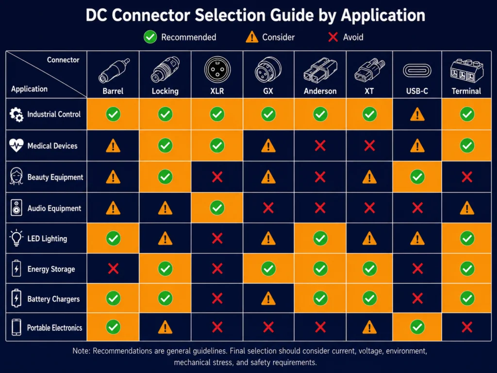
Application-Based Recommendations
Industrial Control
- Recommended: GX16/20 (locking, high current), Terminal Block (field wiring), Anderson SB (UPS/battery)
- Consider: Locking barrel (lower current, ± 24V control systems)
- Avoid: Standard barrel without locking, USB-C (industrial environments lack ruggedization)
Medical Devices
- Recommended: Locking barrel (thread-lock), XLR (locking + shielding), GX (for higher power)
- Consider: Mini-DIN (combo power + signal for patient monitors)
- Avoid: USB-C (PD negotiation complexity in regulatory context), non-locking connectors for patient-near equipment
Beauty Equipment
- Recommended: Locking barrel (snap-lock for quick disconnect), GX12/16 (for higher-power IPL/laser devices)
- Consider: XLR (shielding for RF devices)
- Avoid: Standard barrel (accidental disconnection during treatment)
Audio Equipment
- Recommended: XLR (standard for professional audio), Locking barrel (studio monitors)
- Consider: USB-C PD (consumer audio), GX (broadcast rack equipment)
- Avoid: Standard barrel in vibration environments
LED Lighting
- Recommended: Terminal block (permanent installation), GX12/16 (signage), Anderson (high-power arrays)
- Consider: Barrel with weatherproof rating (outdoor use)
- Avoid: USB-C (lighting installations are fixed-wire, not designed for PD negotiation)
Energy Storage
- Recommended: Anderson SB (high-current, genderless), XT60/XT90 (battery packs), Ring terminals (battery interconnect)
- Consider: GX20 (enclosed system interface)
- Avoid: Standard barrel (insufficient current), non-locking connectors in vibration
Battery Chargers
- Recommended: XT60/XT90 (high-current battery packs), Anderson (industrial battery systems), Barrel (lower-current consumer chargers with locking preferred)
- Consider: USB-C PD (consumer chargers up to 100–240W)
- Avoid: Single-point barrel for high-rate charging (> 5A continuous)
Portable Electronics
- Recommended: USB-C PD (universal, high cycle life), Barrel (proprietary designs, cost-optimized)
- Consider: Locking barrel (ruggedized portable gear)
- Avoid: Large connectors (GX, Anderson) on compact portable devices
Common Connector Mistakes
1. Wrong Inner Diameter
Using a 5.5×2.5 mm plug in a 2.1 mm jack (damage) or a 2.1 mm plug in a 2.5 mm jack (loose, high resistance). Solution: Wire inner diameter into your product spec.
2. Wrong Polarity
Reverse polarity can destroy electronics instantly. Solution: Use polarized connectors where possible. Clearly mark polarity on the adapter and device.
3. Underrated Current
Using a barrel connector rated for 3 A at 13 A continuous load. Solution: Use the selection matrix above and derate for temperature.
4. Excessive Cable Length
Long, thin cables create voltage drops that cause devices to brown out. Solution: Use the downloadable cable gauge calculator (included in this guide’s toolkit).
5. Thin Cable Gauge
Using 22 AWG cable for a 5 A load. Solution: Reference the cable gauge table in Section 2 and the toolkit.
6. No Strain Relief
Relying on the solder joint inside the connector for mechanical support. Solution: Specify overmolded or booted strain relief.
7. No Locking in Vibration Environments
Standard barrel connectors unplug in industrial, medical, or mobile equipment. Solution: Use locking barrel, XLR, or GX connectors.
8. Incorrect Mating Connector
Assuming any 5.5×2.5 mm plug mates with any 5.5×2.5 mm jack. Solution: Request matched samples from your power supply vendor.
9. Using USB-C Without PD Negotiation
Plugging a USB-C adapter into a device expecting a simple 12 V rail. Solution: USB-C requires active PD negotiation—it is not a passive barrel replacement.
10. Assuming Certification Applies to the Connector Alone
A connector on a non-certified cable or from a non-certified manufacturer is not certified. Solution: Verify the entire cable assembly carries the required safety and EMC marks.
OEM Customization Workflow
YHYadapter offers OEM customization of DC output connectors to match your product requirements. The following parameters can be customized:
| Parameter | Options |
|---|---|
| Connector type | Barrel (all sizes), locking barrel, XLR, GX, terminal block, Anderson, custom |
| Connector angle | Straight, right-angle (90°), 45° |
| Locking mechanism | Thread-lock, snap-lock, bayonet, latch (by connector type) |
| Cable length | 0.3–5 m standard; custom lengths available |
| Cable gauge | 14–24 AWG depending on current requirements |
| Cable color | Black, white, grey, custom (volume dependent) |
| Polarity | Center positive, center negative, custom (by application) |
| Pin assignment | For multi-pin connectors, assign per your spec |
| Ferrite core | Clip-on or integrated ferrite for EMI suppression (available by model) |
| Labeling | Custom voltage/current labels, barcodes, logos |
| Packaging | Bulk, individual bag, retail packaging, ESD-safe |
Customization process:
- Submit your connector requirements through the contact form or engineering team
- Receive a custom specification document with mechanical drawings
- Approve samples (typical lead time: 2–4 weeks for first samples)
- Production quantities with full quality assurance testing
Cable Gauge & Current Capacity
Cable gauge selection is often treated as an afterthought in connector specification, but the cable is electrically part of the connector system. An undersized cable negates the performance of a well-chosen connector.
AWG Basics
The American Wire Gauge (AWG) system is the standard for DC power cables in North America. In this system, a smaller number means a thicker wire:
| AWG | Diameter (mm) | Cross Section (mm²) | Approx Metric Equivalent |
|---|---|---|---|
| 14 | 1.63 | 2.08 | 2.0 mm² |
| 16 | 1.29 | 1.31 | 1.5 mm² |
| 18 | 1.02 | 0.823 | 0.75 mm² |
| 20 | 0.812 | 0.518 | 0.5 mm² |
| 22 | 0.644 | 0.326 | 0.34 mm² |
| 24 | 0.511 | 0.205 | 0.2 mm² |
Metric Cable Sizes (mm²)
Outside North America, cable sizes are specified in mm² cross-sectional area. Common metric sizes and their AWG equivalents:
| mm² | Nearest AWG | Typical Current (chassis) |
|---|---|---|
| 0.5 mm² | 20 AWG | 5 A |
| 0.75 mm² | 18 AWG | 8 A |
| 1.0 mm² | 17 AWG | 10 A |
| 1.5 mm² | 16 AWG | 12 A |
| 2.0 mm² | 14 AWG | 17 A |
| 2.5 mm² | 13 AWG | 20 A |
What Determines Current Capacity
The current a cable can safely carry is not a fixed value. It depends on:
- Cable length — Longer cables have higher resistance (R ∝ length), generating more heat and more voltage drop at the same current.
- Ambient temperature — At 50 °C ambient, a cable’s effective current capacity is approximately 70% of its 25 °C rating. At 70 °C, approximately 50%.
- Bundle installation — Cables bundled together trap heat. In a bundle of 5–10 cables, derate current by 30–50%.
- Insulation material — PVC insulation softens at 80–105 °C. Silicone and Teflon (PTFE) insulation withstand 150–200 °C, allowing higher current at the same wire gauge.
- Conductor material — Copper is standard. Aluminum conductors require approximately 1.6× the cross-sectional area for equivalent current.
🛠️ Engineering Tip: Do not rely on a single “max current” number from an online table. Always apply derating factors for your specific cable length, ambient temperature, and bundle configuration. The downloadable toolkit includes a voltage drop and derating calculator customized for OEM cable assemblies.
Cable Flexibility
Flexibility depends on the number and arrangement of conductor strands:
| Stranding | Flexibility | Typical Use |
|---|---|---|
| Solid core | Low | Fixed installations, building wiring |
| 7-strand | Medium | General-purpose power cables |
| 19-strand | High | Flexible power cords, adapters |
| 42+ strand (fine) | Very high | Robot cables, portable equipment |
For external power adapter cables, 19-strand or finer stranding is recommended to withstand repeated bending and coiling.
Long Cable Compensation
When cable length exceeds 3–5 m, voltage drop may require a higher-voltage adapter or a sense-wire configuration:
- Remote sensing — A separate pair of wires measures voltage at the load and adjusts the adapter output to compensate. Common in precision instrumentation.
- Voltage step-up — Specify a slightly higher nominal output voltage (e.g., 12.5 V instead of 12.0 V) to compensate for expected drop at nominal load.
- Thicker cable — Move from 20 AWG to 18 AWG or 16 AWG. This is the simplest and most cost-effective solution for cables under 5 m.
Typical Recommendations
| Application | Voltage | Current | Cable Length | Recommended Gauge |
|---|---|---|---|---|
| Wall plug adapter, consumer | 5–12 V | 1–3 A | 1.0–1.5 m | 20–22 AWG |
| Desktop adapter, general | 12–24 V | 3–5 A | 1.2–1.8 m | 18–20 AWG |
| Desktop adapter, high power | 24–48 V | 5–10 A | 1.2–2.0 m | 16–18 AWG |
| Medical device | 12–24 V | 3–6 A | 2.0–3.0 m | 18 AWG (minimum) |
| Industrial power | 24–48 V | 5–15 A | 2.0–5.0 m | 14–16 AWG |
| Battery charger | 12–48 V | 5–30 A | 0.5–2.0 m | 10–14 AWG |
Voltage Drop Example
A practical example helps illustrate why cable gauge selection matters.
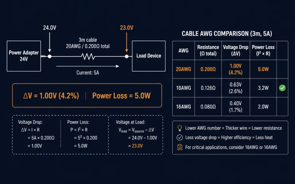
Scenario
- System voltage: 24 VDC
- Load current: 5 A (continuous)
- Cable length: 3 m (from adapter to device)
- Initial cable choice: 20 AWG (common off-the-shelf cable)
Step 1: Calculate Cable Resistance
20 AWG copper wire has a resistance of approximately 0.0333 Ω/m at 25 °C. For a 3 m cable, the total conductor length is 6 m (3 m forward + 3 m return).
Rcable=0.0333Ω/m×6m=0.200Ω
Step 2: Calculate Voltage Drop
Vdrop=I×R=5A×0.200Ω=1.00V
At 5 A through 3 m of 20 AWG cable, the voltage reaching the load is:
Vload=24.0V−1.00V=23.0V
This is a 4.2% voltage drop — acceptable for most 24 V systems (typically within ±5% tolerance), but marginal.
Step 3: Calculate Power Loss
The power dissipated as heat in the cable is:
Ploss=I2×R=(5A)2×0.200Ω=5.0W
Five watts of heat dissipated inside a cable bundle will raise the temperature of the cable and any adjacent wires. In a confined space, this can accelerate insulation aging.
Step 4: Evaluate and Upgrade
| Cable | Resistance (6 m) | Voltage Drop | Power Loss | % Drop | Verdict |
|---|---|---|---|---|---|
| 20 AWG | 0.200 Ω | 1.00 V | 5.0 W | 4.2% | Marginal — acceptable but hot |
| 18 AWG | 0.126 Ω | 0.63 V | 3.2 W | 2.6% | Good — recommended |
| 16 AWG | 0.079 Ω | 0.40 V | 2.0 W | 1.7% | Excellent — over-engineered for this current |
Recommendation: Upgrade from 20 AWG to 18 AWG. This reduces voltage drop from 4.2% to 2.6% and cuts cable power dissipation by 36%, significantly improving system reliability and connector temperature.
🛠️ Engineering Tip: For every OEM cable assembly, calculate voltage drop at the minimum input voltage condition. A 24 V system that operates at 20 V during brownout conditions will experience proportionally higher percentage drop, potentially causing the load to undervoltage-lockout.
Connector Life Cycle
All connectors wear with use. Understanding the life cycle helps select the right connector for the expected number of mating events.
Mating Cycles
Each insertion and removal causes mechanical wear on the contact surfaces:
| Connector Type | Rated Cycles | Failure Mode After Wear |
|---|---|---|
| Standard barrel | 1,000–5,000 | Spring fingers lose tension → intermittent contact → high resistance → overheating |
| Locking barrel (thread) | 500–2,000 | Thread wear → reduced locking force → eventual disconnection under vibration |
| GX (aviation) | 500–1,000 | Thread wear, pin surface erosion |
| XLR | 1,000–5,000 | Latch spring fatigue → reduced retention force |
| USB-C | 10,000 (rated) | CC pin wear → negotiation failure; contact wear → resistance increase |
| Anderson SB | 10,000+ | Contact beam fatigue → reduced normal force |
| Terminal block (screw) | 10–50 (wire insertions) | Thread stripping, conductor crushing |
Contact Oxidation
Metal contacts exposed to air develop a thin oxide layer. For tin-plated contacts, oxidation accelerates above 60 °C and at high humidity, increasing contact resistance by 2–5× over the connector’s lifetime. Gold-plated contacts resist oxidation and maintain stable resistance for 10× more cycles than tin.
Contact Resistance Increase Over Time
A typical barrel connector’s contact resistance profile:
| Life Stage | Contact Resistance | Effect |
|---|---|---|
| New (0 cycles) | 10–20 mΩ | Low loss, minimal heating |
| Mid-life (~2,000 cycles) | 15–30 mΩ | Slight increase, still acceptable |
| End-of-life (~5,000 cycles) | 30–80 mΩ | Noticeable heating; may trigger thermal derating |
| Failed (>5,000 cycles) | >100 mΩ | Intermittent contact, voltage drop, overheating risk |
Environmental Aging
UV exposure, temperature cycling, humidity, and chemical exposure accelerate connector degradation:
- Plastic housings: Become brittle after 5–10 years of UV exposure (outdoor use requires UV-stabilized materials)
- Rubber boots/gaskets: Dry out and crack over 3–5 years in hot, dry environments
- Solder joints: Thermal cycling causes fatigue cracks after 1,000–5,000 cycles
How to Choose Based on Insertion Frequency
| Insertion Frequency | Expected Lifetime | Recommended Connector |
|---|---|---|
| < 1×/month (factory set) | < 100 cycles | Barrel, terminal block, locking barrel |
| 1×/week (periodic service) | < 500 cycles | Locking barrel, GX, XLR |
| 1×/day (daily use) | < 3,000 cycles | XLR, USB-C, Anderson |
| Multiple×/day (frequent) | > 5,000 cycles | USB-C, Anderson (gold-plated) |
Waterproof Connectors
For outdoor, washdown, or wet-environment applications, connectors must be rated for water and dust ingress. The IP (Ingress Protection) rating system defines these levels.
IP Rating Guide
| Rating | Solids Protection | Water Protection | Connector Examples |
|---|---|---|---|
| IP54 | Limited dust ingress (not dust-tight) | Splashing water from any direction | GX16 with seal, some locking barrels |
| IP65 | Dust-tight (no dust ingress) | Low-pressure water jets (6.3 mm nozzle) | GX20 with O-ring, MIL-spec circular connectors |
| IP67 | Dust-tight | Temporary immersion (1 m, 30 min) | Sealed circular connectors, overmolded barrels |
| IP68 | Dust-tight | Continuous immersion (depth specified by manufacturer) | Underwater connectors, submarine-rated |
Typical Industries
- Outdoor LED Lighting (IP65–IP67) — GX16/GX20 with sealing gaskets, overmolded cable assemblies
- Energy Storage (IP54–IP65) — Anderson with sealed housings, GX with O-ring
- Industrial Automation (IP54–IP67) — Terminal blocks in IP-rated enclosures, sealed circular connectors
- Medical Mobile Equipment (IP54) — Locking connectors with boot seals, splash-proof designs
- Marine / Off-Road (IP67–IP68) — Specialty sealed connectors, overmolded cable assemblies
Critical Clarification
A connector’s IP rating does not make the entire adapter system waterproof. An IP67-rated connector attached to a non-rated adapter body or a cable with unsealed entry points does not create an IP67 system. The entire power delivery chain — adapter housing, cable, connector, and device interface — must be designed and tested as a sealed system for any IP rating to be meaningful.
If waterproofing is critical, specify:
- IP-rated connector with mating seal
- Overmolded or sealed cable-to-connector transition
- IP-rated adapter enclosure
- Sealed device interface (if applicable)
- System-level IP testing, not component-only
EMI Considerations
Connector and cable selection directly affects electromagnetic interference (EMI) performance. A well-shielded power supply can fail radiated emissions testing because of a poorly chosen output connector and cable assembly.
Cable Radiation
The DC output cable acts as an antenna. The effectiveness of this antenna depends on:
- Cable length — Cables near ¼-wavelength of the switching frequency harmonics radiate most efficiently. For a 65 kHz switcher, harmonics at 1–30 MHz are the primary concern.
- Cable routing — Cables routed near apertures or unshielded openings radiate more.
- Cable symmetry — Twisted-pair or coaxial DC cables have lower radiation than parallel conductors.
Grounding and Shielding
| Connector Type | Shielding | Ground Path | EMC Performance |
|---|---|---|---|
| Standard barrel | No | Single wire (GND pin) | Poor — cable acts as monopole antenna |
| Locking barrel | Optional | GND wire + ferrule | Moderate |
| XLR (metal shell) | Yes | Shell connected to GND | Good — shell provides 360° shielding |
| GX (metal shell) | Yes | Shell connected to GND | Good — threaded shell provides continuous ground |
| USB-C (metal shell) | Yes | Shell + GND pins | Good — shielded by design |
| Anderson | No | Wire only | Poor — no shielding |
| Terminal block | No | Wire only | Poor — depends on enclosure shielding |
Ferrite Cores
A ferrite core (clip-on or integrated) placed near the connector end of the cable suppresses common-mode conducted emissions:
- Effective range: 10–300 MHz (most relevant for switching power supply EMI)
- Placement: As close to the connector as possible
- Limitation: Adds cost and bulk; not all OEM products have space for a ferrite
YHYadapter offers integrated ferrite cores as an OEM option on select models. Available by application and target market.
Cable Routing Best Practices
- Keep DC cables away from AC input cables and signal cables
- Avoid running DC cables parallel to unshielded data lines
- Use twisted-pair or coaxial DC cables for sensitive applications
- Minimize cable length — every extra meter increases antenna efficiency
- Ground cable shield at the adapter end only (single-point ground to avoid ground loops)
🛠️ Engineering Tip: If your product fails radiated emissions testing at the output cable frequency, first check the connector ground path. A floating or high-impedance ground at the connector is the #1 cause of cable-related EMI failures. Ensure the connector shell (if metal) has a low-impedance path to the adapter’s ground plane.
Certification Considerations
Connectors used in OEM power supply assemblies must comply with applicable safety and environmental regulations. Certification does not apply to the connector alone — it applies to the connector as part of the complete cable assembly.
UL 62368-1 (IT/AV Equipment Safety)
Key connector-related requirements:
- Creepage and clearance: Minimum distances between live parts of opposite polarity and between live parts and accessible surfaces. For 30–60 VDC circuits, typical minimum clearance is 0.4–1.0 mm depending on pollution degree.
- Temperature rise: Connector contacts and housings must not exceed specified temperature limits under normal and fault conditions (typically 70–105 °C rise above ambient for plastic materials).
- Strain relief: The connector-to-cable junction must withstand a 30 N pull test for 1 minute without damage to the connection.
- Mating force: Connectors must not exceed specified insertion/withdrawal forces to prevent damage.
IEC 60601-1 (Medical Electrical Equipment)
Medical applications add stricter requirements:
- Leakage current: The connector and cable assembly contribute to total patient leakage current. Limit is typically 100–300 µA for patient-near equipment (BF/CF type).
- 2×MOPP (Means of Patient Protection): Connector creepage and clearance must meet 4 mm (clearance) / 8 mm (creepage) for 250 VAC working voltage at 2×MOPP.
- Locking requirement: Medical connectors in patient-near equipment must resist accidental disconnection.
- Biocompatibility: Connector materials in contact with patients may require ISO 10993 testing.
CE (EU) and FCC (US)
- CE — EMC Directive 2014/30/EU: Connector shielding design affects radiated emissions. A poorly shielded connector can cause the entire product to fail EN 55011/55032 testing.
- CE — LVD 2014/35/EU: Connector safety (creepage, clearance, temperature rise) is assessed as part of the complete power supply.
- FCC Part 15 (Class A / Class B): Connector and cable assembly design directly impacts radiated and conducted emissions.
RoHS and REACH
- RoHS (2011/65/EU): Connector materials must not contain restricted substances (lead, mercury, cadmium, hexavalent chromium, PBB, PBDE, DEHP, BBP, DBP, DIBP) above threshold limits.
- REACH (EC 1907/2006): Connector suppliers must declare any Substances of Very High Concern (SVHC) present above 0.1% weight.
Important Note
Connector certification alone does not guarantee complete product compliance. A connector with UL Component Recognition (UL 1977) is not the same as a certified power supply assembly bearing a UL 62368-1 listing mark. The connector is one component in a larger system — the complete adapter assembly must be certified as a whole.
When requesting certification documentation from your power supply vendor, ensure the certificate covers:
- The complete adapter model (not just the connector)
- The applicable end-product standard (UL 62368-1, IEC 60601-1, etc.)
- The specific configuration (connector type, cable length, gauge) used in your product
OEM Connector Decision Tree
This decision tree guides OEM engineers from application requirements to the recommended connector type. Use it as a starting point, then verify with vendor datasheets.
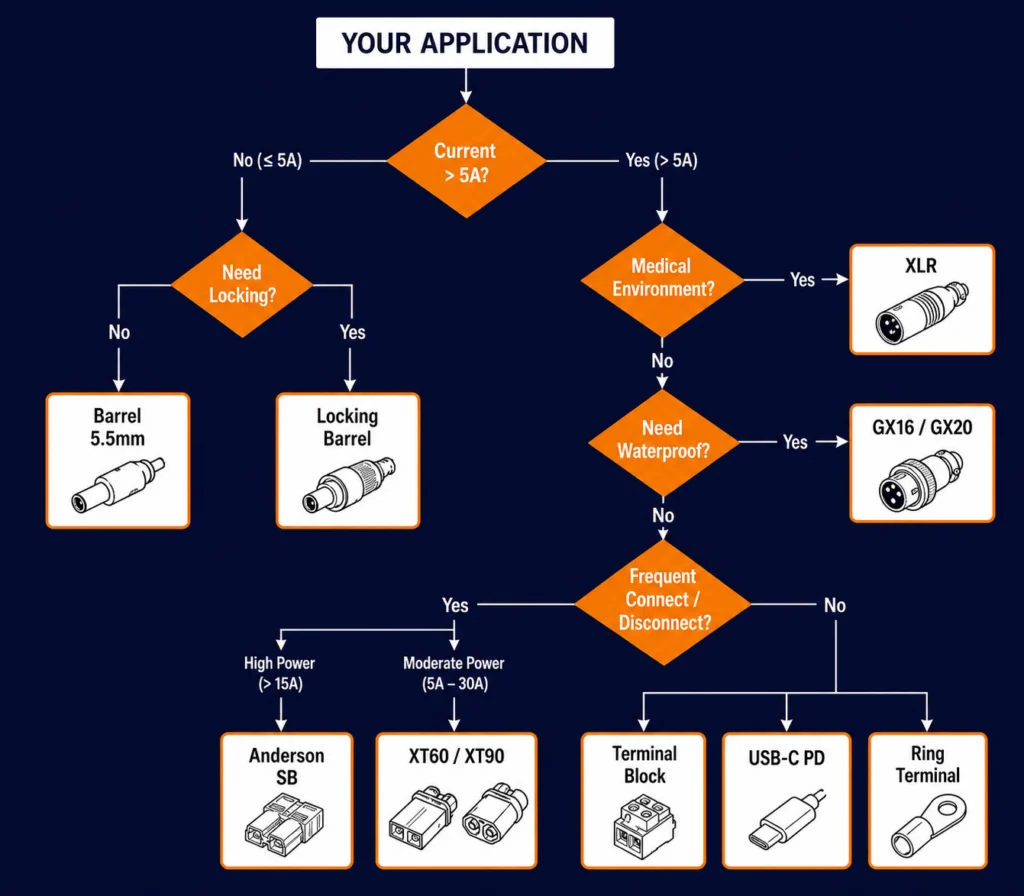
Expanded Engineering Matrix
Full engineering comparison across 12 connector types and 8 selection parameters:
| Connector Type | Typical Current | Voltage (Typ) | Locking | Waterproof Option | Mating Cycles | Relative Cost | Customization | Best Applications |
|---|---|---|---|---|---|---|---|---|
| 5.5×2.1 Barrel | 2–5 A | ≤ 30 V | No | No (unsealed) | 1,000–5,000 | $ (Low) | High | Consumer, low-power adapters |
| 5.5×2.5 Barrel | 3–7 A | ≤ 30 V | No | Limited (boot) | 1,000–5,000 | $ (Low) | High | Desktop adapters, general OEM |
| Locking Barrel | 2–7 A | ≤ 30 V | Thread/Snap | Limited (boot seal) | 500–2,000 | $$ (Medium) | Medium | Medical, lab, mobile |
| Mini-DIN | 1–2 A/pin | ≤ 30 V | Friction + key | No | 1,000–5,000 | $$ (Medium) | Medium | Signal + power combo |
| XLR (3/4/5) | 3–6 A (std) | ≤ 50 V | Latch | No (std) | 1,000–5,000 | $$$ (Medium-High) | Low-Medium | Audio, broadcast, some medical |
| GX12/16/20 | 3–15 A | ≤ 250 V (rated) | Thread | Yes (IP67) | 500–1,000 | $$-$$$ (Medium-High) | Medium | Industrial, outdoor, power output |
| Anderson SB | 15–50 A | ≤ 600 V | Genderless housing | Optional (sealed housing) | 10,000+ | $$$ (Medium-High) | Low | High-current DC, batteries, UPS |
| XT60/XT90 | 30–90 A | ≤ 60 V (typ) | Friction + polarized | No | 500–1,000 | $$ (Medium) | Low | Battery packs, chargers (hobby/OEM) |
| Molex/JST | 2–9 A | ≤ 250 V | Locking tab | No | 50–200 | $ (Low) | Low | Internal harness, PCB connectors |
| Terminal Block | 10–50 A | ≤ 600 V | Screw/Spring | Enclosure-dependent | 10–50 (wire) | $ (Low) | Medium | Open-frame, industrial, field wiring |
| USB-C PD | 3–5 A | 5–48 V (PD 3.1) | Friction + CC | No (std) | 10,000 | $$ (Medium) | Low (standard only) | Consumer, PD-capable equipment |
| Ring/Fork | 10–60 A | ≤ 600 V | Screw/Stud | No | 5–20 | $ (Low) | Low | Battery terminals, grounding, distribution |
🛠️ Engineering Tip: The expanded matrix includes voltage, waterproofing, mating cycles, cost, and customization — five additional dimensions beyond the compact matrix. Use the compact matrix for quick reference and the expanded matrix for detailed vendor evaluation.
OEM Requirement Checklist
Use this checklist when submitting a connector specification to your power supply vendor. Completing this upfront avoids sample revision cycles.
Electrical Requirements
| # | Parameter | Your Specification | Notes |
|---|---|---|---|
| 1 | Output Voltage | ___ VDC | Nominal value |
| 2 | Output Current | ___ A | Continuous rating |
| 3 | Peak Current (if applicable) | ___ A for ___ ms/s | Transient requirement |
| 4 | Polarity | Center Positive / Center Negative / Custom | For barrel connectors |
| 5 | Pin Assignment | Pin 1: ___, Pin 2: ___, etc. | For multi-pin connectors |
Mechanical Requirements
| # | Parameter | Your Specification | Notes |
|---|---|---|---|
| 6 | Connector Type | Barrel / Locking / XLR / GX / Anderson / USB-C / Terminal Block / Custom | Primary type |
| 7 | Connector Size / Pin Count | ___ mm (OD×ID) or ___ pins | For barrel: OD×ID in mm |
| 8 | Connector Angle | Straight / Right-Angle / 45° | Cable exit direction |
| 9 | Cable Length | ___ m | From adapter to connector tip |
| 10 | Cable Gauge | ___ AWG | Based on current + length calculation |
| 11 | Cable Color | Black / White / Grey / Custom | |
| 12 | Locking Required? | Yes / No | If yes: Thread / Snap / Bayonet / Latch |
| 13 | Strain Relief | Overmolded / Boot / None |
Environmental Requirements
| # | Parameter | Your Specification | Notes |
|---|---|---|---|
| 14 | Operating Temperature | ___ °C to ___ °C | Adapter + connector |
| 15 | IP Rating Required? | IP54 / IP65 / IP67 / IP68 / None | System-level requirement |
| 16 | Outdoor Use? | Yes / No | Affects UV stabilization |
| 17 | Washdown / Harsh Environment? | Yes / No | Sealing requirement |
Compliance Requirements
| # | Parameter | Your Specification | Notes |
|---|---|---|---|
| 18 | Target Certifications | UL / CE / FCC / PSE / CCC / KC / RCM / Medical (IEC 60601-1) | List all |
| 19 | RoHS Required? | Yes / No | |
| 20 | REACH Compliance? | Yes / No |
Production Requirements
| # | Parameter | Your Specification | Notes |
|---|---|---|---|
| 21 | Labeling | Voltage / Current / Logo / Custom text | Specify exact text |
| 22 | Packaging | Bulk / Individual bag / Retail / ESD-safe | |
| 23 | Sample Quantity | ___ units | For first article inspection |
| 24 | Mass Production Quantity | ___ units/year | Annual estimate |
| 25 | Target Sample Date | ___ (date) | |
| 26 | Target Production Date | ___ (date) |
📞 CTA Block — Need a Custom DC Connector Solution?
Our engineering team can design and integrate the right DC output connector for your OEM product — whether standard, locking, or fully custom.
- Request a Quote → — Submit your connector requirements for a detailed quotation
- Talk to an Engineer → — Discuss connector options with our design team
Downloadable Connector Selection Toolkit
We have prepared a comprehensive toolkit to help you evaluate and select DC connectors for your OEM project.
📥 Download the DC Connector Selection Checklist (.xlsx): /resources/downloads/dc-connector-selection-checklist.xlsx
The toolkit includes four worksheets:
Sheet 1 — Connector Selection Checklist A 25-point checklist covering voltage, current, locking, environmental, certification, and integration requirements.
Sheet 2 — Connector Comparison Matrix Side-by-side evaluation template for comparing 6 connector options across 15 parameters.
Sheet 3 — Cable Gauge / Current Planning Calculator for voltage drop at different cable lengths, gauges, and load currents.
Sheet 4 — Supplier Verification Checklist for verifying connector quality, certification, and test reports.
(Gated download — name and email required. Delivered instantly.)
Related Resources
System Note: Related Resources in this article are statically listed for the initial publication. Under the YKOS Relationship Engine (planned), all related products, guides, and certifications will be auto-populated through Knowledge Relationships.
🔌 Related Products
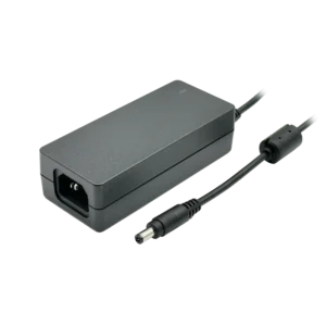
65W Desktop Adapter, Level VI, 5.5×2.5 mm
100–240 VAC input, 65 W output. Standard 5.5×2.5 mm barrel connector.
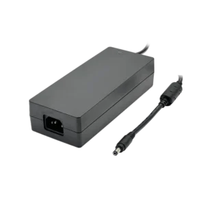
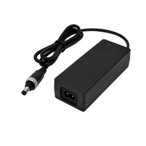
60W Medical Desktop, Locking Connector
Medical-grade IEC 60601-1 certified with locking DC connector option.
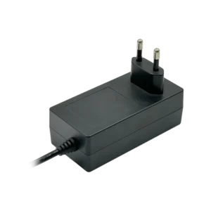
60W Wall Plug Adapter
Fixed EU plug wall adapter, 60 W output, Compact form factor with barrel connector for space-constrained designs.
🏭 Related Applications
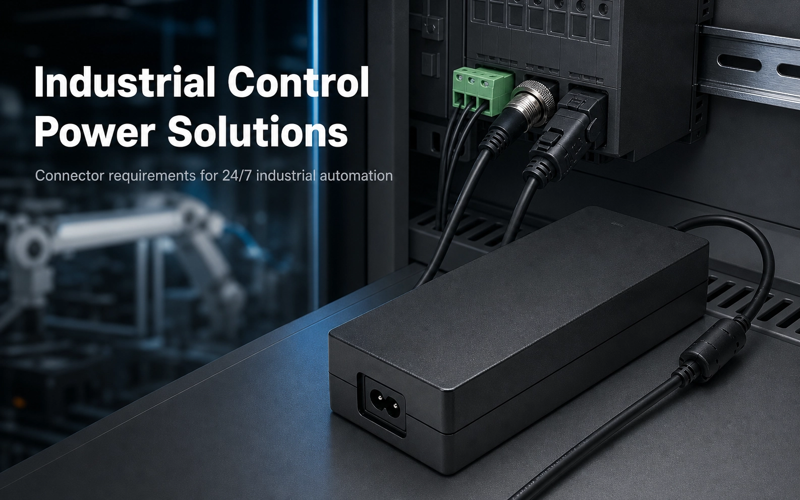
Industrial Control Power Solutions
Connector requirements for 24/7 industrial automation: terminal blocks, GX connectors, vibration-resistant locking options.
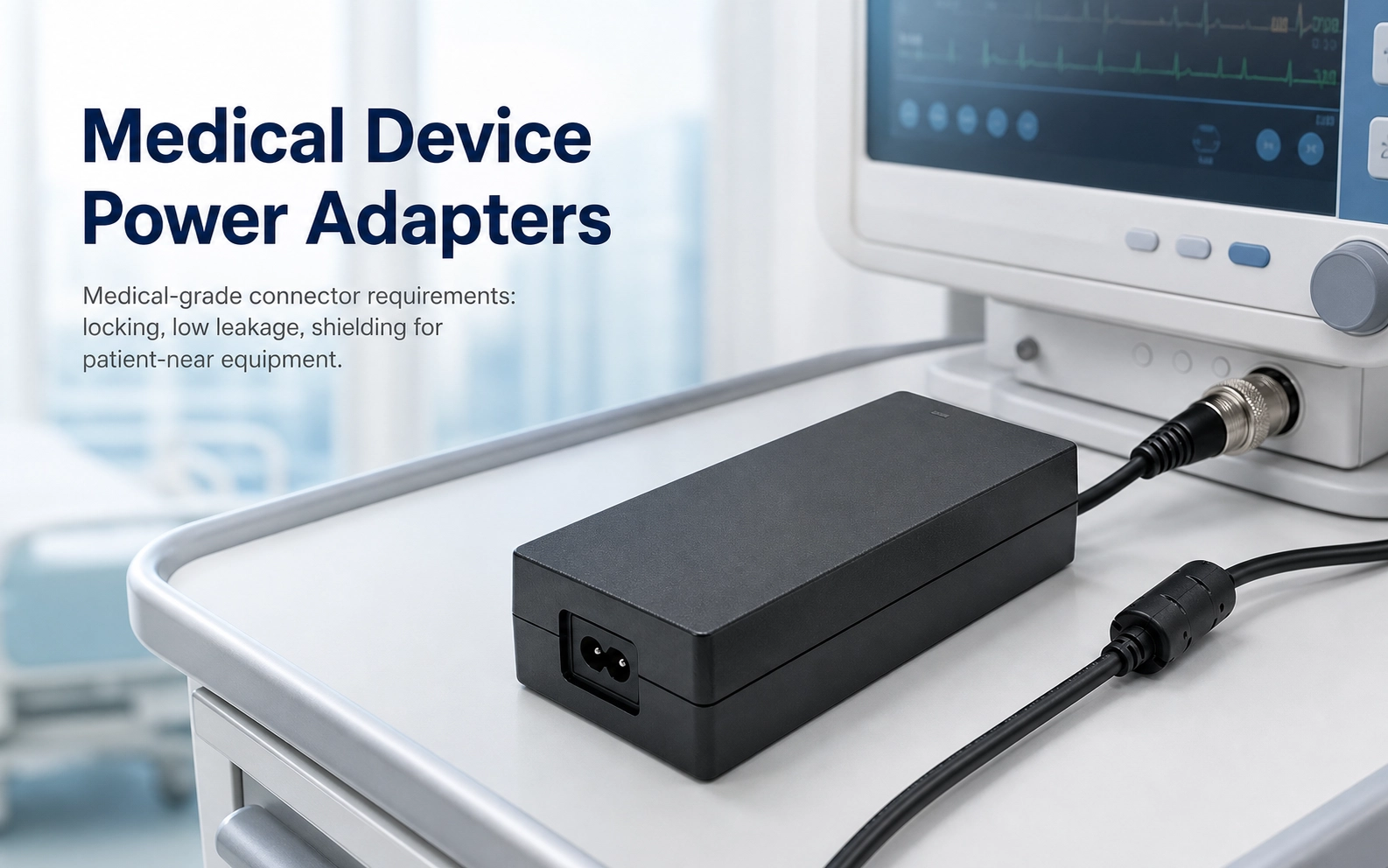
Medical Device Power Adapters
Medical-grade connector requirements: locking, low leakage, shielding for patient-near equipment.
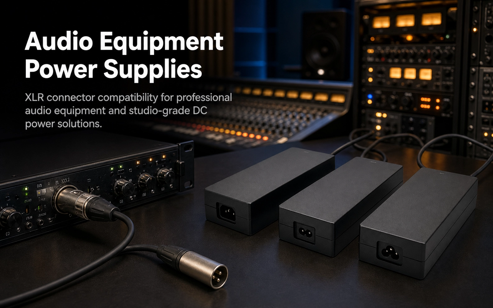
Audio Equipment Power Supplies
XLR connector compatibility for professional audio equipment and studio-grade DC power solutions.

Beauty Equipment Power Supplies
Locking connector requirements for IPL, RF, and laser beauty devices in treatment-room environments.
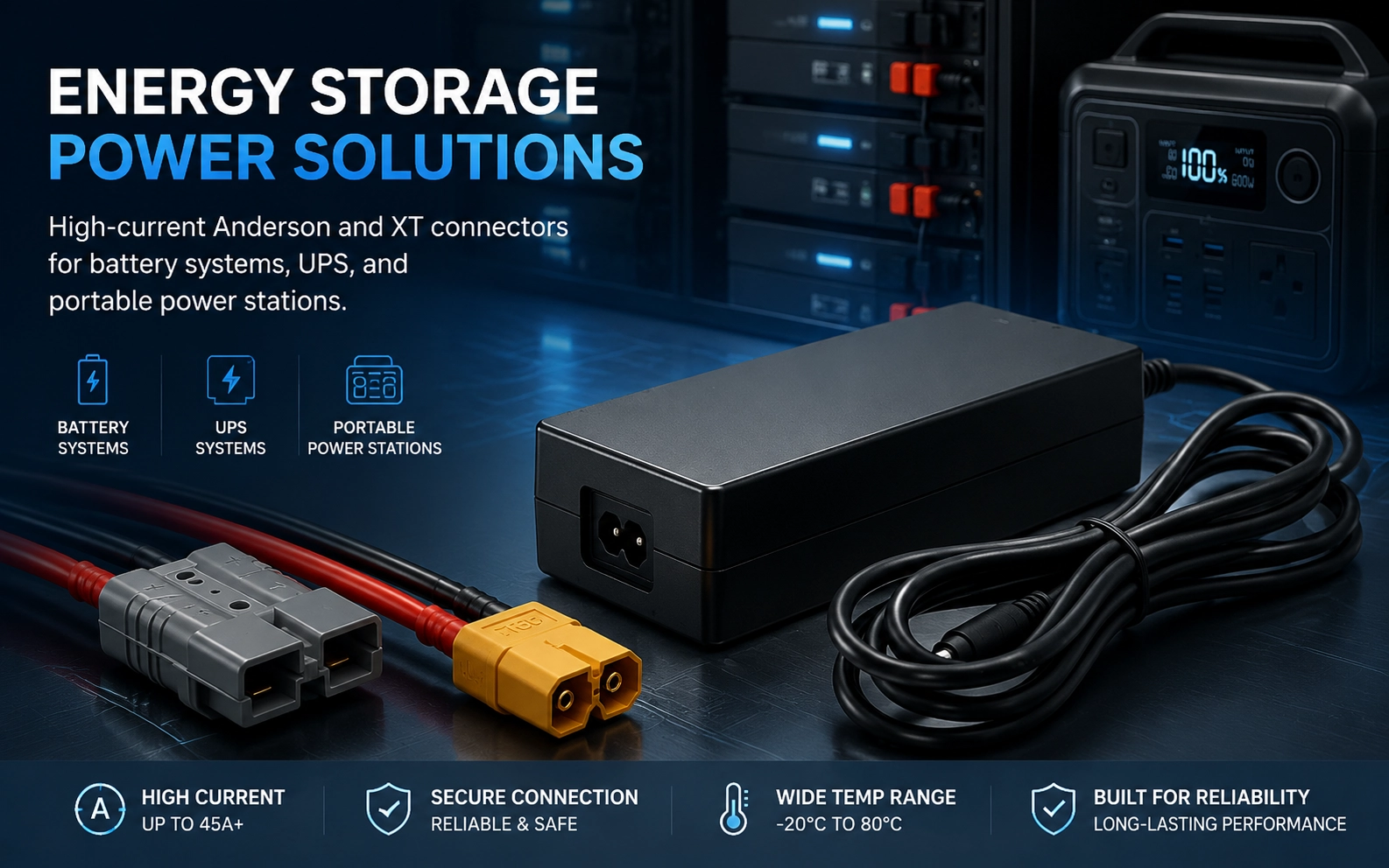
Energy Storage Power Solutions
High-current Anderson and XT connectors for battery systems, UPS, and portable power stations.
📖 Related Guides
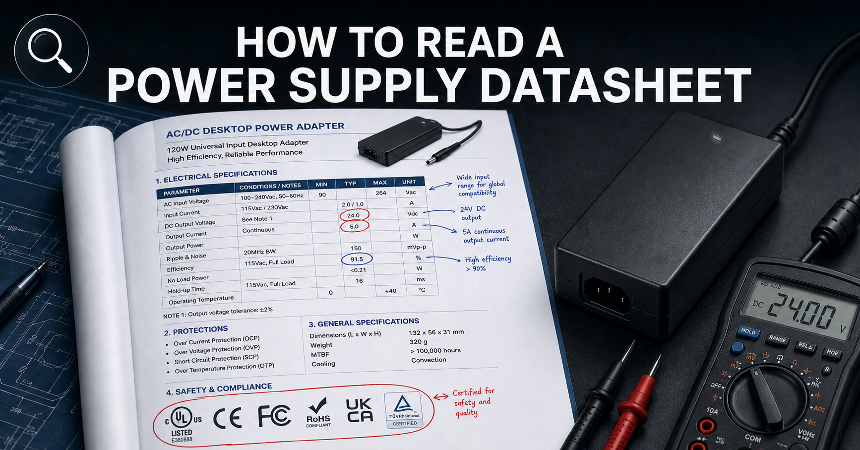
How to Read a Power Supply Datasheet
Learn how to evaluate connector specifications in a datasheet — current ratings, derating curves, certification verification.
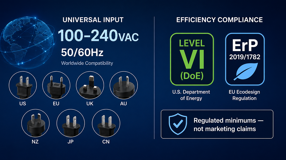
Power Supply Efficiency Ratings
Understand how connector resistance and voltage drop affect overall system efficiency and thermal performance.
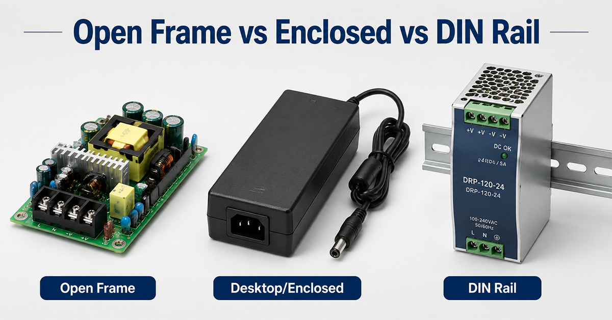
Open Frame vs Enclosed vs DIN Rail Power Supplies
Compare connector types used across different power supply form factors — terminal blocks, barrel, and custom.
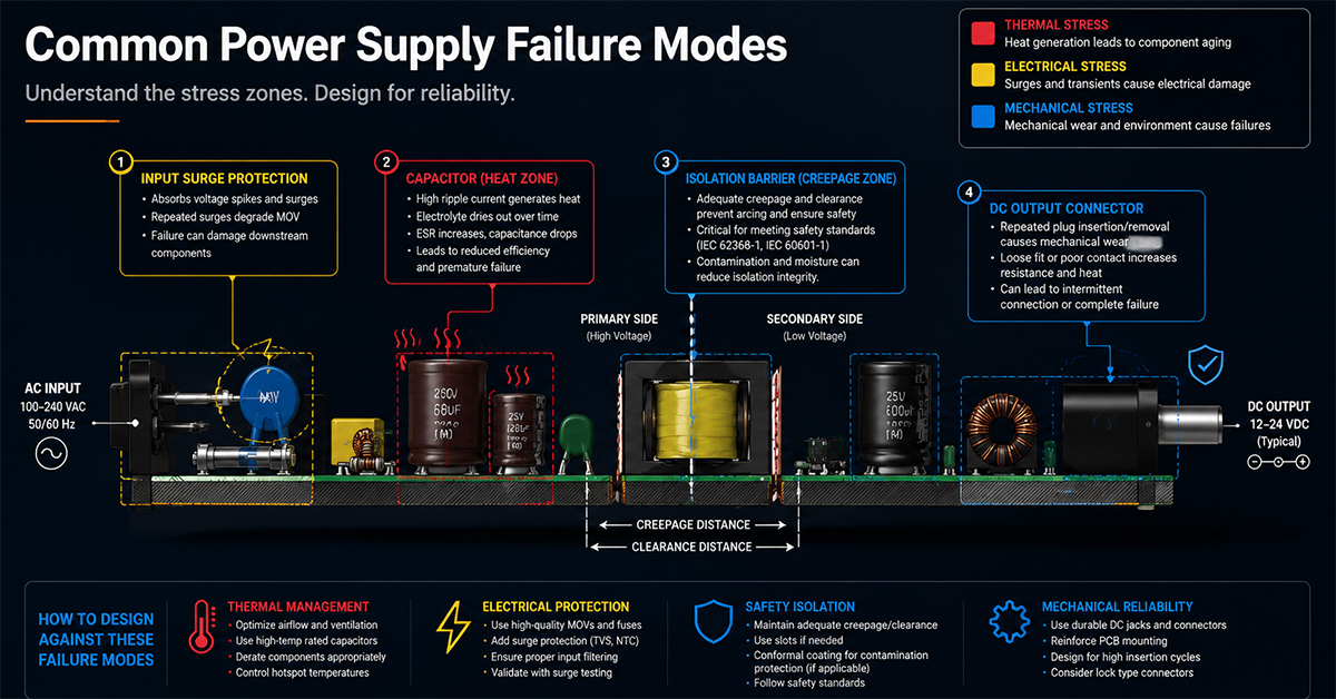
Common Power Supply Failure Modes
Connector-related failure modes: intermittent contact, overheating, cable damage, and mechanical fatigue.
✅ Related Certifications
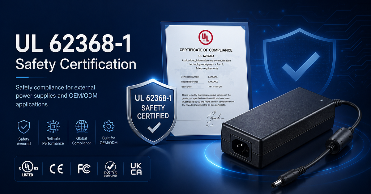
UL 62368-1 Safety Certification
Safety standard covering connector creepage/clearance, temperature rise, and strain relief requirements for IT/AV equipment power adapters.
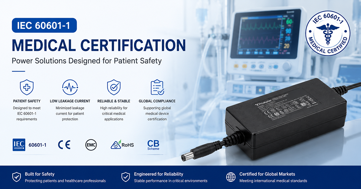
IEC 60601-1 Medical Certification
Medical connector requirements: locking, leakage current limits, and patient-near safety for DC connectors.
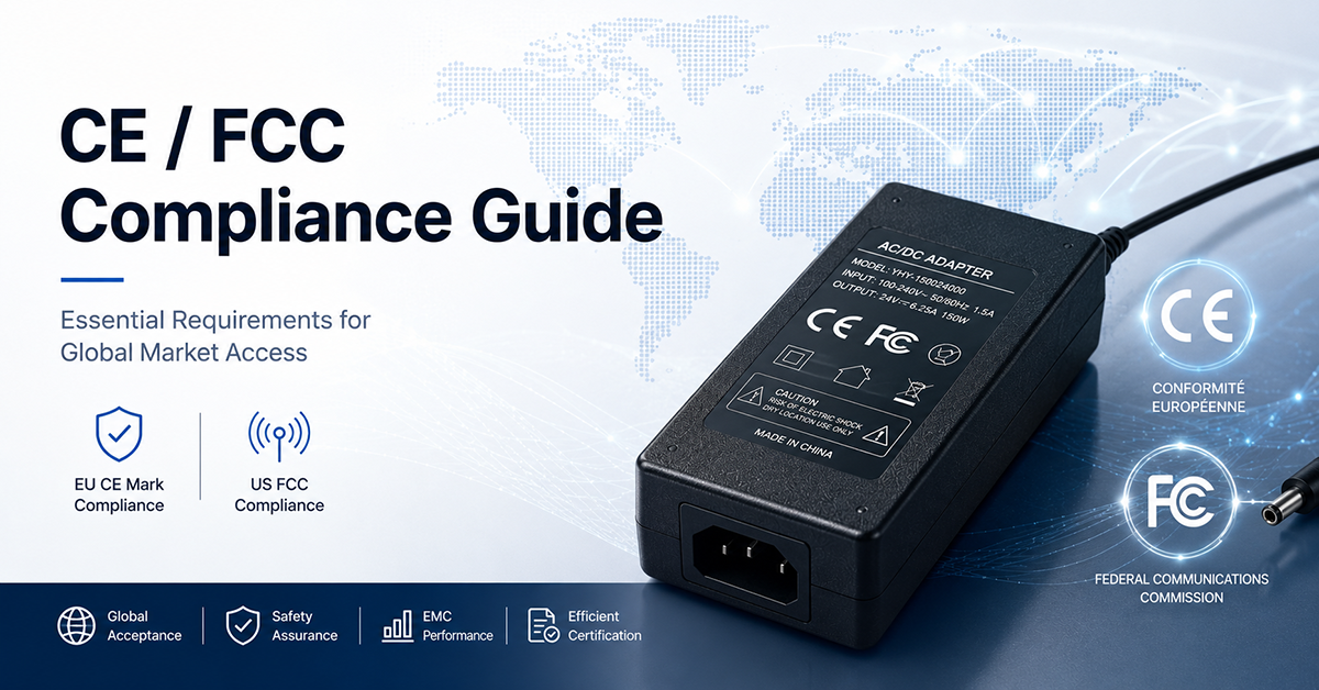
CE / FCC Compliance Guide
EMC requirements for connector cable assemblies, shielding effectiveness, and radiated emissions.
Related Downloads
DC Connector Selection Checklist
Detailed 4-sheet Excel workbook with 25-point checklist, 6-connector comparison matrix, cable gauge calculator, and supplier verification.
Datasheet Comparison Checklist
Standardized 20+ parameter template for comparing power supply datasheets across vendors. From PF02.
Certification Overview
Quick-reference guide to global power adapter certification marks — UL, CE, PSE, CCC, KC, RCM, BIS — with verification steps.
Frequently Asked Questions
Q1: Is 5.5×2.1 mm compatible with 5.5×2.5 mm?
A: No. While they share the same outer diameter (5.5 mm), they have different inner diameters (2.1 mm vs 2.5 mm). A 2.5 mm plug is too large for a 2.1 mm jack and may damage it. A 2.1 mm plug in a 2.5 mm jack will have a loose, high-resistance connection. They should not be considered interchangeable.
Q2: How much current can a barrel connector safely carry?
A: It depends on the size, contact material, ambient temperature, and whether the load is continuous or intermittent. As a general guideline: 5.5×2.5 mm connectors are suitable for 3–7 A continuous at room temperature. At temperatures above 40 °C, derate by 20–30%. For sustained loads above 5 A, consider locking barrel, XLR, GX, or Anderson connectors.
Q3: When should I use a locking connector?
A: Use a locking connector when your application involves vibration (industrial equipment, mobile devices), user handling (medical beauty equipment), or mission-critical connections where accidental disconnection is unacceptable. Thread-locking barrels are good for medical and lab equipment. GX and Anderson connectors suit industrial and high-current applications. XLR suits professional audio and broadcast.
Q4: Can the connector polarity be customized?
A: Yes. YHYadapter can configure barrel connectors with center-positive or center-negative polarity. For multi-pin connectors (XLR, GX, DIN), pin assignments can be customized to match your product specification. Always document polarity clearly on the adapter label and in the product manual.
Q5: Is USB-C PD interchangeable with a standard DC connector?
A: Not directly. USB-C PD requires active protocol negotiation between the adapter and the device to establish voltage and current. A USB-C adapter cannot simply pass through 12 V or 24 V like a barrel connector. If your device expects a fixed DC voltage, you need a barrel or pin-assigned connector, not USB-C—unless your device includes USB-C PD sink controller hardware.
Q6: Which connector is best for medical devices?
A: Medical devices typically require a locking connector to prevent accidental disconnection during patient procedures. Recommended options include locking barrel (thread-lock) for lower-power devices and GX or XLR for higher-power equipment. All connectors used in medical applications must be verified as part of the IEC 60601-1 system certification, covering leakage current, creepage/clearance, and temperature rise under fault conditions.
Q7: Can cable length affect output voltage?
A: Yes. Every meter of DC cable adds resistance that causes a voltage drop proportional to the load current. At 5 A through 2 m of 20 AWG cable, voltage drop is approximately 0.4 V. In a 5 V system this is significant (8% loss); in a 24 V system it is negligible (1.7%). Always calculate voltage drop for your specific cable length, gauge, and current—use the calculator in the downloadable toolkit.
Q8: What information should I send for a custom connector quote?
A: The most helpful information includes: (1) required voltage and current, (2) connector type preference (barrel, locking, XLR, GX, etc.), (3) preferred connector size or pin count, (4) cable length and gauge, (5) device type and environment, (6) target certifications (UL, CE, medical), and (7) annual volume estimate. Submit your requirements through Request a Quote → and our engineering team will respond with a specification recommendation.
Key Takeaways
- Start with current, then locking, then environment — connector selection should follow this priority order.
- 5.5×2.1 mm and 5.5×2.5 mm are NOT interchangeable — wire the inner diameter into your product spec and verify samples.
- Barrel connectors have practical current limits — above 5 A continuous, switch to locking, XLR, GX, Anderson, or terminal block solutions.
- USB-C PD is not a passive connector — it requires protocol negotiation and cannot be treated as a simple DC barrel replacement.
- “Aviation connector” does not mean aerospace certified — GX connectors are industrial-grade, not MIL-SPEC.
- Cable gauge and length affect delivered voltage — always calculate voltage drop for your application.
- Standard barrel connectors will unplug in vibration — use locking connectors for industrial, medical, and mobile equipment.
- Use the downloadable toolkit — the DC Connector Selection Checklist and comparison matrix make vendor evaluation systematic.
- Customization is available — connector type, angle, cable length, gauge, polarity, and labeling can all be configured for OEM projects.
Conclusion: Selecting the Right DC Connector for Your OEM Product
Choosing the right DC power connector is a balance of electrical requirements (voltage, current, contact resistance), mechanical constraints (panel space, mating cycles, locking), environmental conditions (temperature, moisture, vibration), and cost.
The two most common mistakes OEM teams make are:
- Over-relying on barrel connectors for applications beyond their safe current or environmental limits.
- Treating USB-C as a universal adapter without accounting for PD negotiation complexity.
For most standard OEM applications up to 5 A continuous, a properly specified 5.5×2.5 mm barrel connector is adequate and cost-effective. As current, vibration, or safety requirements increase, move to locking barrel, XLR, GX, Anderson, or terminal block connectors.
When in doubt, consult the downloadable selection toolkit and our engineering team for a connector specification review.
- Request a Quote → — Submit your connector requirements for a detailed quotation
- Talk to an Engineer → — Discuss connector options with our design team
📥 Download the DC Connector Selection Toolkit — Ready-to-use Excel workbook with checklist, comparison matrix, cable gauge calculator, and supplier verification. Download Now →