Introduction
Thermal management is a critical part of power supply design because the energy lost during AC/DC conversion is primarily dissipated as heat. As power density increases, controlling that heat becomes increasingly important for maintaining output capability, component reliability, and long-term performance.
For example, a 120W desktop power adapter operating at 92% efficiency requires approximately 130.4W of input power and dissipates about 10.4W as internal power loss:
Input Power = 120W ÷ 0.92 ≈ 130.4W
Power Loss = 130.4W − 120W ≈ 10.4W
That heat must travel from heat-generating components through the PCB, thermal interface materials, internal structure, and enclosure before it can be transferred to the surrounding environment. Ambient temperature, airflow, enclosure design, component placement, operating load, and installation conditions all influence how effectively this heat can be removed.
For OEM product designers and sourcing engineers, thermal performance should therefore be evaluated alongside output power, efficiency, size, and reliability—not treated as a power supply specification in isolation.
This guide explains the key thermal considerations when selecting or customizing an AC/DC power supply, including sources of power loss, heat-transfer paths, thermal derating, ambient-temperature effects, component lifetime, enclosure design, and practical methods for evaluating thermal performance in the final application.
How Does Heat Generation Scale with Power Supply Efficiency?
The heat generated inside a power adapter is directly related to its conversion efficiency and output power. For a given output power, higher efficiency means less electrical energy is lost inside the power supply and therefore less heat must be dissipated.
The relationship can be expressed as:
P_loss = P_out × ((1 − η) / η)
Where:
- P_loss = internal power loss
- P_out = output power
- η = conversion efficiency expressed as a decimal
Example: 120W Power Adapter
At a constant 120W output, relatively small improvements in efficiency can significantly reduce internal power loss:
| Efficiency | Input Power | Internal Power Loss |
|---|---|---|
| 88% | 136.4W | 16.4W |
| 92% | 130.4W | 10.4W |
| 96% | 125.0W | 5.0W |
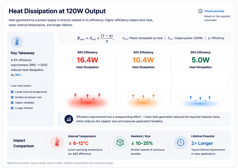
Improving efficiency from 88% to 92% reduces internal power loss by approximately 36%, even though the efficiency rating increases by only four percentage points.
At 96% efficiency, the internal loss is approximately 5W—less than one-third of the loss produced by the same 120W adapter operating at 88% efficiency.
Where Does the Heat Come From?
Power loss is distributed across multiple components and mechanisms within the adapter, including:
- Switching losses in MOSFETs or GaN devices
- Conduction losses in switching and rectification stages
- Transformer core and winding losses
- PFC-stage losses where applicable
- PCB and interconnection resistance
- Capacitor ESR and other passive-component losses
The dominant heat sources depend on the power level, topology, switching frequency, semiconductor technology, input voltage, output voltage, and operating load.
For this reason, total efficiency alone does not identify where the thermal hotspots will occur.
Why This Matters
- Lower internal power loss reduces the amount of heat that must be transferred from components to the surrounding environment.
- This can provide greater flexibility for: Higher Power Density → Lower Component Temperature → More Thermal Margin → Smaller Enclosure Potential
- However, higher efficiency does not automatically guarantee a smaller or cooler adapter. Actual temperature performance also depends on component placement, PCB design, thermal interfaces, enclosure materials, airflow, ambient temperature, and installation conditions.
What OEMs Should Do Now
- When comparing power adapters, review the efficiency curve across the expected operating range, rather than relying only on a single efficiency value.
- Useful operating points may include: 10% → 25% → 50% → 75% → 100% Load
For thermal evaluation, calculate or measure power loss at the application’s actual operating point and verify performance under relevant worst-case conditions, including:
- Maximum continuous load
- Minimum and maximum AC input voltage
- Maximum expected ambient temperature
- Enclosed or restricted-airflow installation
- Expected duty cycle
Engineering Note
Efficiency tells you how much power is lost. Thermal design determines where that heat goes and how hot the components become.
Two 120W adapters with the same efficiency can still have different hotspot temperatures because their internal thermal resistance, component placement, enclosure construction, and heat-transfer paths are different.
Q: Which component is typically the hottest inside a power adapter?
A: There is no universal answer. Depending on the topology and operating condition, thermal hotspots may occur at the primary switching device, secondary rectifier or synchronous MOSFET, transformer, PFC stage, or other high-loss components.
A properly designed adapter should be evaluated through thermal testing at the relevant input voltage, load, ambient temperature, and installation condition.
Q: Does efficiency change with AC input voltage?
A: Yes. Input voltage affects RMS current, conduction losses, switching behavior, PFC operation, and other loss mechanisms. As a result, efficiency can vary across the rated AC input range.
OEMs should review efficiency data at the input voltages relevant to the target market and verify thermal performance under the operating condition that produces the most demanding combination of electrical and thermal stress.
Useful Links
→ Desktop Adapter Series
→ Industrial Power Adapter Selection Guide
How to Read and Apply a Thermal Derating Curve
A thermal derating curve shows how much continuous output power a power adapter can safely deliver as ambient temperature changes. It is one of the most important specifications for applications operating in elevated-temperature or restricted-airflow environments.
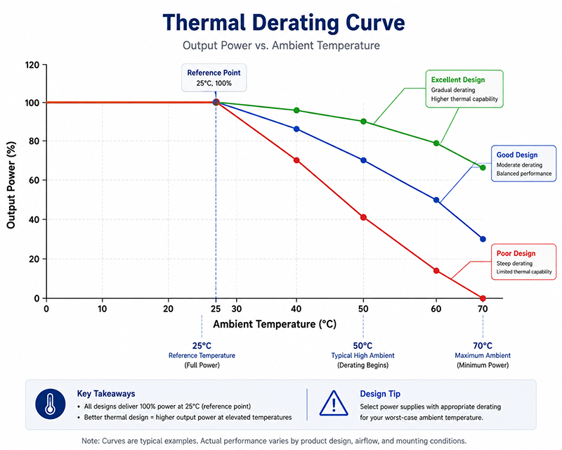
A 120W adapter may deliver its full rated output under normal conditions but require reduced loading as ambient temperature rises. For this reason, the usable power at the actual operating temperature can be more important than the nameplate wattage alone.
Understanding a Derating Curve
A typical curve plots:
X-axis → Ambient Temperature (°C)
Y-axis → Available Output Power (% of Rated Power)
Consider the following illustrative example for a 120W desktop adapter:
| Ambient Temperature | Available Output* | Equivalent Power |
|---|---|---|
| 25°C | 100% | 120W |
| 40°C | 100% | 120W |
| 50°C | 80% | 96W |
| 60°C | 60% | 72W |
| 70°C | Outside specified operating range | — |
Illustrative example only. Actual derating limits and operating-temperature ranges are model-specific and should be verified from the manufacturer’s datasheet.
In this example, an application requiring 90W would be comfortably within the adapter’s capability at 40°C, but at 60°C the same 120W adapter would be limited to approximately 72W and would no longer be suitable for continuous operation at that load.
Why Does Output Power Decrease at Higher Temperatures?
As ambient temperature rises, the temperature difference between internal components and the surrounding environment decreases, making it more difficult for the adapter to reject internally generated heat.
To keep critical components within their allowable temperature limits, the permitted continuous output power may need to be reduced.
The shape of the derating curve depends on factors such as:
- Conversion efficiency
- Power density
- Semiconductor losses
- Transformer and magnetic-component temperature limits
- Capacitor temperature ratings
- PCB thermal design
- Enclosure material and construction
- Thermal interface design
- Airflow and installation conditions
Depending on the design, a derating curve may be linear, segmented, or more complex.
Derating Is Not Thermal Protection
Thermal derating and overtemperature protection (OTP) describe different behaviors.
Thermal Derating
Defines the continuous load the adapter is designed to support under specified temperature conditions.
Overtemperature Protection
Responds when an internal temperature exceeds a defined protection threshold, typically by reducing or shutting down the output according to the protection design.
An adapter should normally be selected so that it operates within its published derating envelope, rather than relying on OTP to manage normal high-temperature operation.
Installation Conditions Matter
The ambient temperature around the adapter may be significantly different from the general room temperature.
Thermal performance can be affected by:
- Enclosed equipment compartments
- Restricted airflow
- Nearby heat-generating components
- Mounting orientation
- Surface contact
- Cable and connector placement
- Ventilation openings
- External heat sources
For this reason, OEMs should evaluate the temperature at the adapter’s actual installation location under worst-case operating conditions.
How to Apply a Derating Curve
A practical selection process is:
1. Determine the maximum expected ambient temperature
Measure or estimate the temperature around the adapter under the most demanding expected operating condition.
2. Find that temperature on the derating curve
Read the maximum continuous output available at that ambient temperature.
3. Convert the percentage to usable power
For example, if a 120W adapter is rated for 80% output at the required temperature:
120W × 80% = 96W usable continuous output
4. Compare it with the actual load
Verify that the available derated output exceeds the application’s continuous load while providing appropriate engineering margin for load variation and operating conditions.
Engineering Note
Do not select a power adapter based on nameplate wattage alone. Select it based on the continuous power available at the application’s actual operating temperature.
A 150W adapter with stronger high-temperature performance may provide more usable power in a hot enclosure than a nominally higher-rated adapter with aggressive thermal derating.
Q: What does “full rated output up to 40°C” mean?
A: It means the adapter is specified to provide 100% of its rated continuous output under the manufacturer’s defined test conditions up to 40°C ambient.
It does not indicate what happens above 40°C. For high-temperature applications, the complete derating curve and maximum operating-temperature specification should also be reviewed.
Q: Can I estimate performance between published temperature points?
A: Only when the manufacturer’s documentation indicates that interpolation is appropriate. A straight line between two published points may provide an engineering estimate for a linear derating region, but it should not replace the manufacturer’s specified operating limits or thermal validation in the final application.
Useful Links
How Does Operating Temperature Affect Component Lifetime?
Operating temperature is one of the most important factors influencing long-term power supply reliability. Higher temperature accelerates several aging mechanisms, particularly in aluminum electrolytic capacitors, while also increasing semiconductor losses and thermal stress throughout the power supply.
Electrolytic Capacitor Lifetime
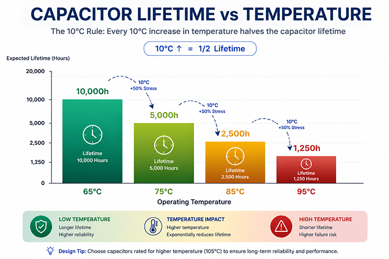
For aluminum electrolytic capacitors, lifetime is commonly estimated using an Arrhenius-based relationship. A widely used engineering approximation is the 10°C rule:
For each 10°C reduction in capacitor core temperature, expected lifetime may approximately double.
However, this is a rule of thumb rather than a universal guarantee. Actual lifetime depends on the capacitor series, rated lifetime, applied voltage, ripple current, internal temperature, and manufacturer-specific lifetime model.
For example, consider a capacitor rated for 2,000 hours at 105°C:
| Capacitor Core Temperature | Approx. Lifetime* |
|---|---|
| 105°C | 2,000 h |
| 95°C | 4,000 h |
| 85°C | 8,000 h |
| 75°C | 16,000 h |
| 65°C | 32,000 h |
Illustrative estimate using the 10°C lifetime-doubling rule. Actual lifetime should be calculated using the capacitor manufacturer’s specified model.
This demonstrates why reducing internal hotspot temperature can have a major effect on service life.
Temperature Affects More Than Capacitors
Other power supply components are also influenced by temperature:
- MOSFETs and rectifiers: Conduction losses generally increase as junction temperature rises, although the exact behavior depends on the device.
- Optocouplers: CTR and other electrical characteristics can change with temperature and aging, affecting feedback design margin.
- Transformers and inductors: Winding resistance increases with temperature, while magnetic properties vary with core material and operating point.
- Solder joints and interconnections: Repeated thermal cycling can create mechanical stress over long service periods.
- Insulation materials and polymers: Long-term exposure to elevated temperature can accelerate material aging.
For this reason, power supply lifetime should not be evaluated from a single component rating alone.
Why This Matters
- The published operating-temperature range indicates the conditions in which the power supply is intended to operate according to its specification. It does not, by itself, define the expected service life at every temperature within that range.
- Two adapters with the same output rating can have very different long-term thermal performance because of differences in: Component Grade → Efficiency → Thermal Design → Hotspot Temperature → Derating → Reliability Margin
- The actual temperature of critical internal components is therefore more meaningful than ambient temperature alone when evaluating lifetime.
What OEMs Should Do Now
For applications requiring extended service life, OEMs should review:
- Capacitor temperature rating and rated lifetime
- Actual capacitor hotspot temperature
- Ripple-current loading
- Semiconductor junction temperature
- Transformer and magnetic-component temperature
- Load derating at elevated ambient temperature
- Enclosure and airflow conditions
- Thermal cycling in the intended duty profile
Where available, request thermal test data at full load and worst-case ambient conditions, rather than relying only on the external case temperature.
Engineering Note
Lower temperature generally improves reliability, but component lifetime should be calculated from actual component stress—not from ambient temperature alone.
A 105°C capacitor operating at 70°C may have substantially longer life than the same capacitor operating near its maximum temperature, but the result also depends on its rated lifetime, ripple current, voltage stress, and internal heating.
Q: How can power supply lifetime be improved in a high-temperature application?
A: Common approaches include reducing internal power loss, providing greater thermal margin, selecting a higher-capacity platform, improving ventilation, optimizing enclosure heat transfer, and using components with suitable temperature and lifetime ratings.
The most effective solution depends on the actual thermal bottleneck identified during testing.
Q: Are polymer capacitors always better for high-temperature power supplies?
A: No. Polymer capacitors can provide low ESR and strong ripple-current performance, making them useful in some secondary-side applications. However, voltage rating, capacitance, leakage characteristics, cost, physical size, and circuit requirements determine whether they are appropriate.
They are not a universal replacement for aluminum electrolytic capacitors, particularly in high-voltage bulk-energy-storage applications.
Useful Links
→ Wall Plug vs Desktop Power Adapter
→ OEM Power Supply Customization
📞 CTA Block — Need help determining the certification requirements for your target markets?
Contact our engineering team for guidance on certification availability and timelines.
- Request a Quote → — Submit your requirements for a detailed quotation
- Talk to an Engineer → — Discuss technical specs with our design team
What Heatsink and Enclosure Design Decisions Affect Thermal Performance?
Thermal performance depends not only on how much heat a power adapter generates, but also on how effectively that heat can move from internal components to the surrounding environment.
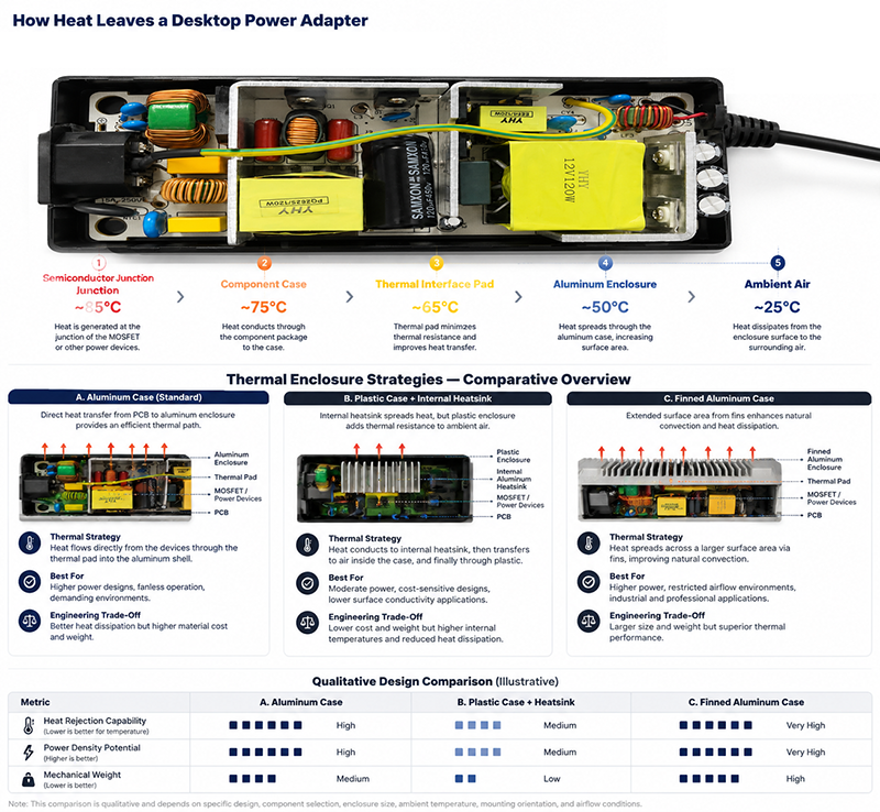
For a semiconductor device, one simplified thermal path can be represented as:
Junction → Package → Thermal Interface → Heatsink / Enclosure → Ambient
In a complete power adapter, however, heat may travel through multiple parallel paths—including the PCB, copper planes, heatsinks, thermal pads, potting materials, internal air, and enclosure.
Each part of the thermal path contributes thermal resistance, which influences the temperature rise of critical components.
Common Enclosure Thermal Strategies
Desktop power adapters may use several different approaches to thermal management.
| Thermal Strategy | How It Works | Key Considerations |
|---|---|---|
| Plastic Enclosure | Internal heat is transferred through the PCB, internal air, thermal interfaces, and enclosure | Electrical insulation, enclosure temperature, internal hotspots, airflow, and power density |
| Plastic Enclosure + Internal Heatsink | High-loss components transfer heat to an internal metal heatsink before heat reaches the enclosure and ambient air | Heatsink placement, thermal interface resistance, airflow, and enclosure design |
| Aluminum Enclosure | The enclosure can become part of the thermal path, allowing selected components to transfer heat toward a larger external surface | Electrical insulation, thermal pads, surface temperature, grounding, mechanical design, and user accessibility |
| Finned Metal Enclosure | Increased external surface area can improve natural convection when the geometry and installation conditions are appropriate | Fin spacing, orientation, airflow, dust, mechanical integration, and accessible surface temperature |
No enclosure material is inherently superior in every application. Thermal performance depends on the complete design rather than the enclosure material alone.
Thermal Interfaces Matter
Even when an aluminum enclosure or internal heatsink is used, heat transfer depends heavily on the interfaces between components.
Common thermal interface solutions include:
- Thermal pads
- Insulating films
- Thermally conductive adhesives
- Gap fillers
- Potting compounds
- Mechanical clamps or mounting hardware
The effectiveness of these interfaces depends on thermal conductivity, thickness, contact area, compression, electrical insulation requirements, and long-term mechanical stability.
A high-performance enclosure cannot compensate for a poorly designed thermal path between the heat source and the enclosure.
Enclosure Material vs. Thermal Design
Aluminum generally offers much higher thermal conductivity than common engineering plastics, making it useful when the enclosure is intentionally designed to spread and dissipate heat.
However, a metal enclosure also introduces additional considerations:
Thermal Performance → Electrical Insulation → Touch Temperature → Grounding → Mechanical Design → Compliance
Plastic enclosures provide electrical insulation and design flexibility, but transferring heat through the enclosure may require careful internal thermal design.
For this reason, enclosure selection should be based on the electrical, thermal, mechanical, safety, and environmental requirements of the complete application.
Mounting and Airflow
Natural convection depends on how heated air moves around the adapter.
Thermal performance may change when the power supply is:
- Installed horizontally or vertically
- Mounted against another surface
- Placed inside an enclosure
- Surrounded by other heat-generating equipment
- Operated with restricted clearance
- Exposed to forced airflow
OEMs should therefore evaluate the adapter in an installation condition representative of the final product rather than assuming free-air datasheet performance will remain unchanged after integration.
Surface Temperature & Safety
A lower internal component temperature does not necessarily mean a lower enclosure surface temperature.
In designs where the enclosure is intentionally used as a heat spreader, improved heat transfer from internal components can increase external case temperature while reducing semiconductor or capacitor hotspot temperature.
This can be beneficial for internal reliability, but accessible surface temperatures must remain within the limits applicable to the product, material, operating condition, and relevant safety standard.
What OEMs Should Evaluate
When thermal performance is important, review:
Power Loss → Internal Hotspots → Thermal Interfaces → Enclosure → Installation → Ambient
Useful manufacturer data may include:
- Case-temperature measurements
- Internal hotspot measurements
- Thermal derating curves
- Test ambient temperature
- Input voltage and output load
- Mounting orientation
- Airflow conditions
- Thermal images or test reports
The test conditions should always be reviewed together with the reported temperature values.
Engineering Note
A metal enclosure does not automatically make a power adapter thermally superior. The complete thermal path determines performance.
A well-designed plastic enclosure with efficient internal heat spreading may outperform a poorly coupled aluminum enclosure. Conversely, an aluminum enclosure can provide an effective thermal path when high-loss components are properly coupled to it and the external installation allows sufficient heat rejection.
Q: Can an external heatsink be added to a plastic power adapter?
A: It may provide limited benefit unless the adapter was designed with an effective thermal path from the internal heat sources to the external mounting surface. Simply attaching a heatsink to the outside of a plastic enclosure does not guarantee meaningful reduction in internal hotspot temperature.
For demanding applications, it is generally better to select or design the power supply around the required thermal conditions from the beginning.
Q: Do ventilation openings improve thermal performance?
A: They can improve natural or forced airflow in some designs, but the result depends on opening location, internal layout, orientation, pressure differences, and surrounding airflow.
Ventilation also affects other design considerations such as dust ingress, liquid protection, electrical safety, mechanical protection, and EMC, so it should be treated as part of the complete enclosure design rather than as an isolated thermal solution.
How to Perform a Basic Thermal Assessment for Your Application
OEM engineers can perform a preliminary thermal assessment before selecting a power adapter by combining the application’s operating conditions with manufacturer thermal data.
The goal is not to predict every internal component temperature precisely, but to determine whether the selected adapter has sufficient thermal and power margin for the intended installation before prototype validation.
Step 1: Determine the Worst-Case Ambient Temperature
Start with the maximum temperature expected at the adapter’s actual installation location, not the general room temperature.
Consider factors such as:
- Enclosed cabinets or equipment compartments
- Nearby heat-generating components
- Restricted airflow
- Outdoor or solar exposure
- Ventilation or HVAC conditions
- Continuous operating load
- Seasonal temperature variation
Whenever possible, use measurements from a representative enclosure or prototype rather than applying a fixed temperature offset.
Result: Tamb,max = Maximum expected local ambient temperature
Step 2: Estimate Power Loss
Use the adapter’s efficiency at the relevant operating point to estimate internal power loss:
Ploss = Pout × ((1 − η) / η)
For example, a 120W adapter operating at 92% efficiency dissipates approximately:
120W × ((1 − 0.92) / 0.92) ≈ 10.4W
This value represents the total internal power loss—not the temperature rise.
The resulting component and enclosure temperatures depend on how effectively that heat is transferred through the adapter’s thermal paths.
Step 3: Check the Thermal Derating Curve
Find the maximum continuous output available at Tamb,max using the manufacturer’s published derating data.
For example:
Rated Power = 120W
Available Output at Required Ambient = 80%
Usable Continuous Power = 120W × 0.80 = 96W
Compare this value with the application’s actual continuous load.
The selected adapter should remain within its published operating and derating limits while providing appropriate engineering margin for load variation and application conditions.
Step 4: Review the Installation Conditions
Compare the manufacturer’s thermal test conditions with the final application.
Check:
| Parameter | Manufacturer Test | Final Application |
|---|---|---|
| Ambient Temperature | Datasheet condition | Actual local ambient |
| Output Load | Test load | Continuous / peak load |
| AC Input | Test input voltage | Target-market input range |
| Orientation | Test orientation | Final mounting position |
| Airflow | Free air / defined airflow | Actual ventilation |
| Surroundings | Open test environment | Cabinet / enclosure / nearby heat sources |
A datasheet temperature result is only meaningful when its test conditions are understood.
Step 5: Identify Critical Thermal Points
Do not treat the entire adapter as having one temperature.
Depending on the design, important thermal points may include:
- Primary switching semiconductor
- PFC components where applicable
- Transformer or inductor
- Secondary rectifier or synchronous MOSFET
- Electrolytic capacitors
- Thermal interface or heatsink
- Enclosure hotspot
- DC connector and output cable at high current
The hottest enclosure location is not necessarily the hottest internal component.
Step 6: Validate the Prototype
The preliminary assessment should be followed by physical thermal testing under representative worst-case conditions.
A basic validation may include:
**Maximum Expected Ambient
- Representative AC Input
- Maximum Continuous Load
- Actual Mounting Orientation
- Final Enclosure / Airflow**
Allow the system to reach thermal steady state before recording temperatures.
Measurements can be taken using appropriately installed thermocouples and, where useful, thermal imaging.
Thermocouple vs. Thermal Camera
A thermal camera is useful for locating surface hotspots across the adapter, PCB, enclosure, and surrounding equipment.
Thermocouples are useful for monitoring specific accessible measurement points over time.
Neither method should be used to infer semiconductor junction temperature directly unless the measurement method and thermal model support that calculation.
Thermal imaging also requires appropriate emissivity settings and measurement technique, particularly when measuring reflective metal surfaces.
A Simple OEM Thermal Assessment
A practical screening workflow is:
1. Maximum Ambient
↓
2. Actual Load
↓
3. Efficiency → Power Loss
↓
4. Derating Curve → Available Power
↓
5. Installation Conditions
↓
6. Prototype Thermal Test
↓
7. Verify Thermal Margin
This provides a more reliable basis for power adapter selection than using rated wattage alone.
What OEMs Should Record
A simple thermal assessment worksheet can include:
| Example | Estimated Self-Heating |
|---|---|
| 120W aluminum-case desktop adapter at 92% | ≈15–20°C |
| 65W plastic-case desktop adapter at 88% | ≈20–30°C |
| 48W wall plug adapter at 88% | ≈25–35°C |
The actual acceptance limits should come from the adapter specification, component ratings, applicable safety requirements, and the OEM application’s reliability targets.
Engineering Note
Thermal calculations are a screening tool. Prototype testing under representative worst-case conditions is the final validation.
Efficiency calculations can estimate how much heat is generated, and derating curves can indicate allowable output power, but neither can fully predict internal hotspot temperatures after the adapter is integrated into the final equipment.
Q: Can I calculate adapter temperature from efficiency alone?
A: No. Efficiency allows you to calculate total internal power loss, but temperature rise depends on the thermal resistance between each heat source and the surrounding environment.
Two adapters dissipating the same 10W of internal loss can reach different component temperatures because of differences in PCB design, thermal interfaces, enclosure construction, airflow, and component placement.
Q: What tools are useful for basic thermal validation?
A: Thermocouples, temperature data loggers, and thermal cameras can all be useful depending on the measurement objective.
For OEM evaluation, the most important factor is not the price or type of instrument, but whether the measurement is taken at the correct location, under representative operating conditions, and after the system has reached thermal steady state.
Useful Links
Conclusion
Thermal management is a critical consideration when selecting a power adapter because operating temperature influences usable output power, component stress, and long-term reliability. Evaluating efficiency and power loss, understanding thermal derating, reviewing component temperature limits, and considering the complete heat-transfer path can help OEM engineers identify thermal risks before a power supply is integrated into the final product.
The most effective thermal design is not determined by enclosure material or rated wattage alone. Efficiency, component selection, PCB layout, thermal interfaces, enclosure construction, airflow, ambient temperature, installation conditions, and operating load all contribute to the final thermal performance.
For applications operating in elevated-temperature, enclosed, or restricted-airflow environments, OEM teams should evaluate the adapter under representative worst-case conditions and verify that sufficient thermal and power margin remains throughout the intended operating range.
Thermal Engineering Support from YHYadapter
YHYadapter provides AC/DC power adapters and customized OEM/ODM power solutions for industrial, medical, audio, smart equipment, and other applications with different power and thermal requirements.
Depending on the selected model and project requirements, available options may include different power platforms, enclosure configurations, thermal design approaches, component selections, cable and connector configurations, and application-specific engineering evaluation.
For projects with demanding thermal requirements, our engineering team can work with OEM customers to evaluate output load, efficiency, ambient temperature, installation conditions, derating requirements, and thermal validation needs before the final power solution is confirmed.
Need help evaluating the thermal requirements of your power adapter?
Share your required output power, operating load, maximum ambient temperature, installation conditions, enclosure constraints, and target application with our engineering team to evaluate the most suitable power platform and thermal approach.
Related Engineering Guides
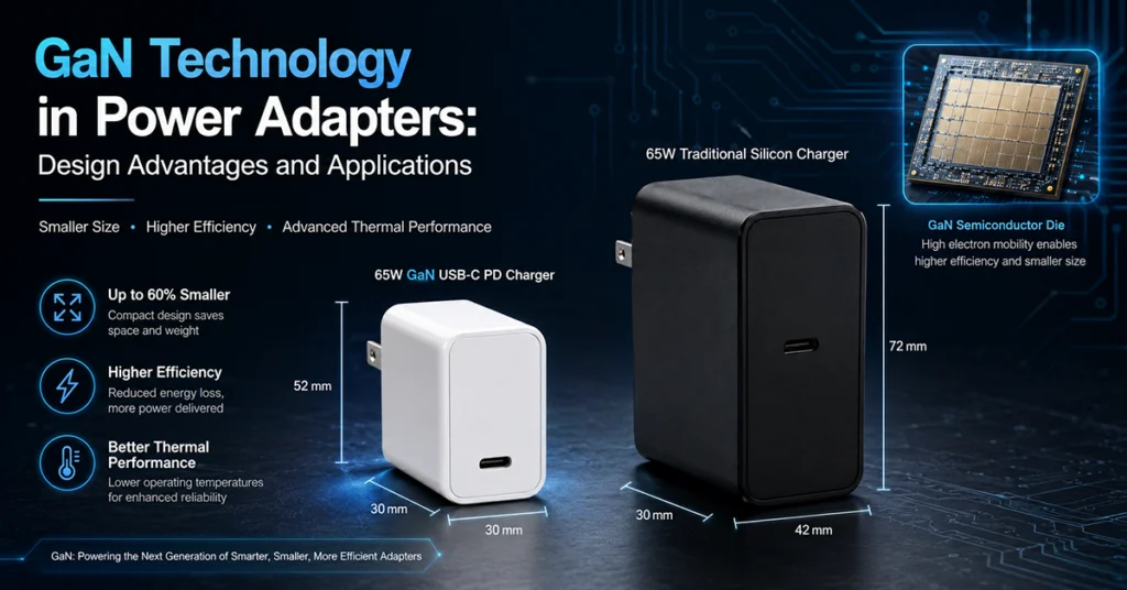
GaN Technology in Power Adapters
Design advantages and thermal implications of higher-efficiency conversion.