
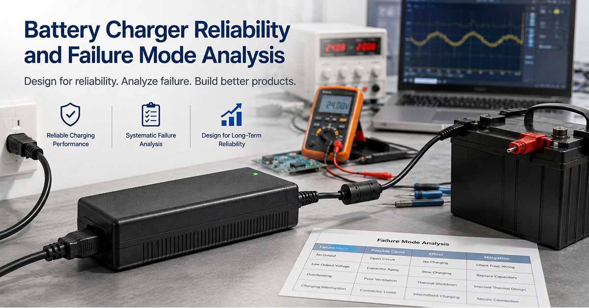
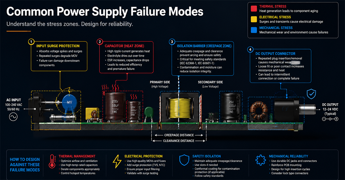
Battery chargers in energy storage systems operate under demanding conditions: high power levels, continuous duty cycles during charging, wide ambient temperature ranges, and exposure to AC mains disturbances. The charger’s reliability directly affects the ESS availability—a charger failure means the battery cannot be recharged, rendering the system non-functional until the charger is repaired or replaced. Understanding common failure modes and their root causes enables OEMs to design for reliability and plan appropriate maintenance strategies.
This guide covers battery charger reliability for energy storage applications: common failure modes, root cause analysis, protection strategies, lifetime estimation, and reliability design practices for ESS OEMs.
Common Charger Failure Modes
Battery charger failures in ESS applications typically result from electrical, thermal, or environmental stress. The following table describes the most common failure modes.
| Failure Mode | Root Cause | Symptoms | Typical Occurrence |
| Electrolytic capacitor degradation | Heat, ripple current, aging | Increased output ripple, reduced charge current, eventual failure | Most common failure mode; accelerated by high operating temperature |
| Input capacitor failure (AC side) | AC line surges, capacitor aging | Blown input fuse, charger fails to start | Can occur suddenly with AC line surge |
| Switching FET failure | Overvoltage, overcurrent, thermal stress | Charger dead, no output | Catastrophic; often preceded by other stress |
| Output rectifier failure | Overcurrent, thermal stress | Reduced output, overheating, eventual failure | More common in high-current chargers |
| Transformer failure | Insulation breakdown, thermal stress | No output, overheating, smoke | Rare but serious; usually caused by sustained overload |
| Control IC failure | Power supply disturbance, ESD, aging | Erratic operation, incorrect charging profile | Less common; can be caused by power quality issues |
| Thermal protection cycling | Inadequate cooling, high ambient, undersized charger | Charger turns on and off in thermal protection loop | Indicates thermal design mismatch |
| Connector failure | Mechanical stress, corrosion, poor contact | Intermittent or no output | Accelerated by vibration, or where contamination is present in the installation |
| Fan failure (active cooled chargers) | Bearing wear, dust accumulation, continuous operation | Overheating, thermal shutdown, reduced lifetime | Predictable wear-out; lifetime depends on fan quality and operating hours |
| PCB contamination | Moisture, dust, corrosive environment | Intermittent faults, leakage current, eventual failure | More common where humidity or contamination is present in the installation |
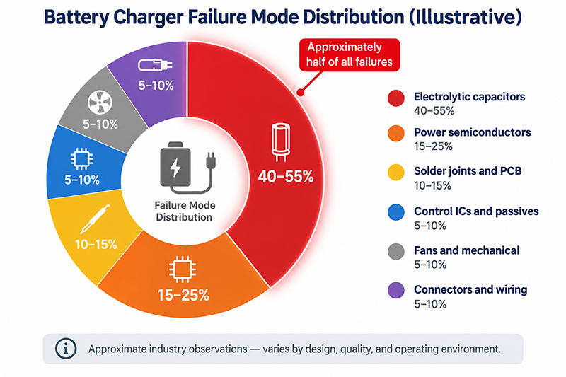
Failure Mode Distribution (Illustrative):
Based on field data from power supply reliability studies, the approximate distribution of failures in battery chargers is:
- Electrolytic capacitors: 40–55% of failures
- Power semiconductors (FETs, rectifiers): 15–25%
- Solder joints and PCB: 10–15%
- Control ICs and passives: 5–10%
- Fans and mechanical: 5–10%
- Connectors and wiring: 5–10%
These are approximate industry observations and may vary by charger design, quality, and operating environment.
Why This Matters
- Electrolytic capacitor degradation accounts for approximately half of all battery charger failures. Capacitor selection and thermal design have the greatest impact on charger reliability.
- Capacitor failure is typically gradual (increased ripple, reduced capacity) rather than sudden. Monitoring output ripple or charge current can provide early warning of capacitor degradation.
- Active cooling (fans) introduces a predictable wear-out mechanism with a defined lifetime (typically 30,000–70,000 hours at rated temperature).
What OEMs Should Do Now
- Select chargers with 105°C-rated electrolytic capacitors from established manufacturers. Verify the capacitor lifetime at the expected operating temperature and ripple current.
- For actively cooled chargers, consider the fan’s expected lifetime and whether it is replaceable without replacing the entire charger.
- Monitor charger output voltage and ripple during routine maintenance. A gradual increase in ripple indicates capacitor degradation.
Thermal Stress and Its Effect on Charger Lifetime
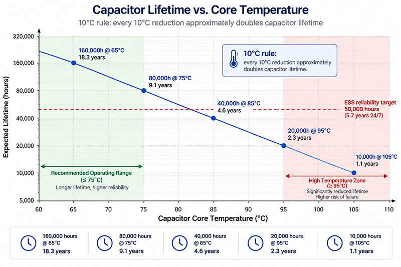
Temperature is the dominant factor affecting charger reliability. The relationship between operating temperature and component lifetime follows established engineering principles.
Capacitor Lifetime vs Temperature:
The lifetime of aluminum electrolytic capacitors follows the Arrhenius relationship: for every 10°C reduction in core temperature, the expected lifetime approximately doubles (and for every 10°C increase, it halves). This approximation is subject to the manufacturer’s lifetime model, ripple current, voltage stress, and actual core temperature.
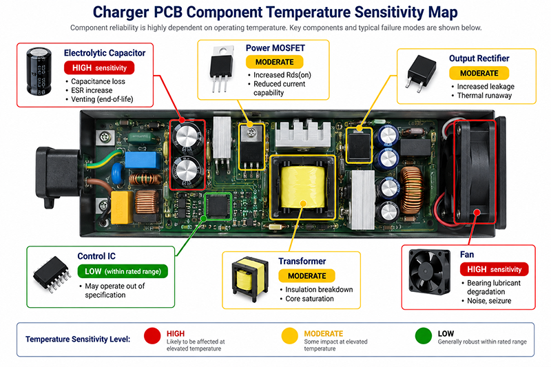
Components Affected by Temperature:
| Component | Temperature Sensitivity | Failure Mode |
| Electrolytic capacitor | High | Capacitance loss, ESR increase, venting |
| Power MOSFET | Moderate | Increased Rds(on), reduced current capability |
| Output rectifier (Schottky) | Moderate | Increased leakage, thermal runaway |
| Transformer | Moderate | Insulation breakdown, core saturation |
| Control IC | Low (within rated range) | May operate out of specification |
| Fan bearings | High | Lubricant degradation, noise, seizure |
Derating for Reliability:
Derating—operating a component below its rated maximum—is a standard reliability design practice:
| Component | Recommended Derating | Benefit |
| Electrolytic capacitor voltage | 80% of rated voltage | Extends capacitor life by reducing voltage stress |
| MOSFET voltage | 80% of Vds(max) | Reduces risk of avalanche breakdown |
| MOSFET current | 70% of rated current | Reduces junction temperature |
| Rectifier current | 70% of rated current | Reduces junction temperature |
| Transformer temperature | Operate below Class B (130°C) rise | Maintains insulation life |
Why This Matters
- A 10°C reduction in capacitor core temperature can approximately double the capacitor’s expected lifetime. Every thermal design improvement—better ventilation, lower ripple current, lower ambient temperature—directly extends charger life.
- Operating a 63V-rated capacitor at 58V (the maximum charge voltage of a 48V LiFePO4 pack) provides a voltage margin of only 8%. The capacitor is operating at 92% of its rated voltage, reducing the derating benefit.
- Component derating is most effective when applied across all temperature-sensitive components, not just the capacitors.
What OEMs Should Do Now
- Measure the charger’s internal component temperatures under worst-case operating conditions (maximum ambient temperature, maximum charge current, maximum AC input voltage).
- Apply derating guidelines across all power components. Select capacitors with voltage rating at least 25% above the maximum operating voltage.
- For continuous-duty ESS chargers, prefer passive cooling over active (fan) cooling where possible. Fanless designs eliminate the fan as a wear-out mechanism.
Protection Strategies for Charger Reliability
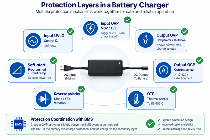
Battery chargers should include protection features that prevent damage from abnormal operating conditions and extend the charger’s service life.
| Protection Feature | What It Prevents | Implementation | Trigger Condition |
| Input overvoltage protection | Surge damage to input stage | MOV, TVS diodes | >110–120% of nominal AC input |
| Input undervoltage lockout | Operation below minimum AC input | Control IC | <85VAC typical for universal input chargers |
| Output overvoltage protection | Battery overcharge damage | OVP comparator + shutdown | Above battery maximum charge voltage |
| Output overcurrent protection | Excessive charge current, short circuit | Current sense + shutdown | >110–120% of rated output current |
| Overtemperature protection | Component damage from overheating | Thermal sensor + shutdown or current reduction | Tc > specified temperature (85–105°C typical) |
| Reverse polarity protection | Charger damage from reversed battery connection | Diode or FET on output | Reverse voltage at output terminals |
| Soft-start | Reduced inrush current at power-on | Programmed current ramp | At each power-on or charge start |
Protection Coordination:
The charger’s protection features should be coordinated with the BMS and the system controller to avoid nuisance trips:
- The BMS may temporarily disable charging for cell balancing or temperature management
- The charger should respond to BMS commands (charge enable/disable, current limit) over the communication interface
- When the BMS requests charge termination, the charger should stop charging and enter a safe idle state
Why This Matters
- A charger without reverse polarity protection can be destroyed instantly if the output leads are connected to the battery with reversed polarity.
- OVP on the charger’s output is a secondary protection layer—the primary overcharge protection is the BMS. The charger’s OVP should activate at a voltage slightly above the BMS’s overcharge threshold.
- OTP should coordinate with the thermal design: brief thermal events (high ambient, reduced airflow) should not cause nuisance shutdown, but sustained overheating must trigger protection.
What OEMs Should Do Now
- Verify that the charger includes all protection features listed above. For custom chargers, specify protection thresholds that align with the BMS and battery specifications.
- Test the charger’s protection features under fault conditions to verify they activate at the correct thresholds and the charger recovers safely after the fault is cleared.
- For chargers with BMS communication, verify the charger responds correctly to BMS commands (charge enable, current limit, charge terminate) under all operating conditions.
Reliability Design Checklist
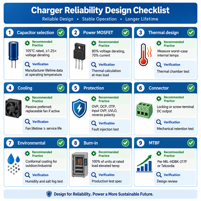
| Area | Design Practice | Verification |
| Capacitor selection | 105°C rated, ≥1.25× voltage derating | Manufacturer lifetime data at operating temperature |
| Power MOSFET selection | 80% voltage derating, 70% current derating | Thermal calculation at maximum load |
| Thermal design | Measure internal temperatures in worst-case conditions | Thermal chamber test at maximum ambient + load |
| Cooling | Passive preferred; if active, replaceable fan | Fan lifetime ≥ charger expected service life |
| Protection | All six protections: OVP, OCP, OTP, OVP input, UVLO, reverse polarity | Fault injection test |
| Connector | Locking or screw-terminal for DC output | Mechanical retention test |
| Environmental | Conformal coating where the installation requires it | Humidity and contamination testing as applicable |
| Burn-in | 100% full-load burn-in aging test | Production test specification |
| MTBF calculation | Per MIL-HDBK-217F or Telcordia at expected operating temperature | Design review |
Frequently Asked Questions
How long should a battery charger last in an ESS application?
Charger lifetime depends on the operating temperature, load profile, and component quality. A well-designed charger with 105°C-rated capacitors operating at 40°C ambient, with adequate derating, may achieve 50,000–100,000 hours of operation. This corresponds to 5.7–11.4 years of continuous 24/7 operation. Higher ambient temperature or sustained high load reduces this lifetime.
What is the most effective way to extend battery charger life?
Reducing the charger’s internal operating temperature is the most effective single improvement. Every 10°C reduction in capacitor core temperature approximately doubles capacitor lifetime. Methods to reduce temperature include: derating the charger (using a charger with higher power rating), improving ventilation, reducing ambient temperature, and using passive cooling.
How do I monitor battery charger health in an installed ESS?
The BMS or system controller should monitor the charger’s output voltage and current during charging. A gradual increase in output ripple (measurable as current fluctuation during CV mode) or a decrease in charge current at the same battery voltage can indicate capacitor degradation. Some advanced chargers provide health monitoring outputs or communication data that includes status and warning flags.
Which failure mode matters most in a charger used for long-duty operation?
Thermal stress on the electrolytic capacitors is a common contributor, because it accumulates rather than appearing suddenly. Higher capacitor temperatures may significantly shorten service life, and the specific relationship depends on the component and the operating conditions.
How can a design reduce thermal stress on the charging side?
By keeping the thermal path deliberate: define the internal ambient, keep the supply out of the hottest region where the layout allows, and treat the duty cycle — not the brief peak — as the design case.
CONCLUSION
Battery charger reliability in energy storage systems is determined primarily by thermal design, component selection, and protection features. Electrolytic capacitor degradation is the dominant failure mode, driven by operating temperature and ripple current. Derating power components, selecting 105°C-rated capacitors, using passive cooling where possible, and implementing comprehensive protection features (OVP, OCP, OTP, reverse polarity) are the most effective strategies for extending charger service life. Regular monitoring of output voltage and ripple provides early warning of capacitor degradation before failure occurs.
Discuss Your Audio Equipment Power Requirements →
Related Resources
🔌 Related Products
🏭 Related Applications
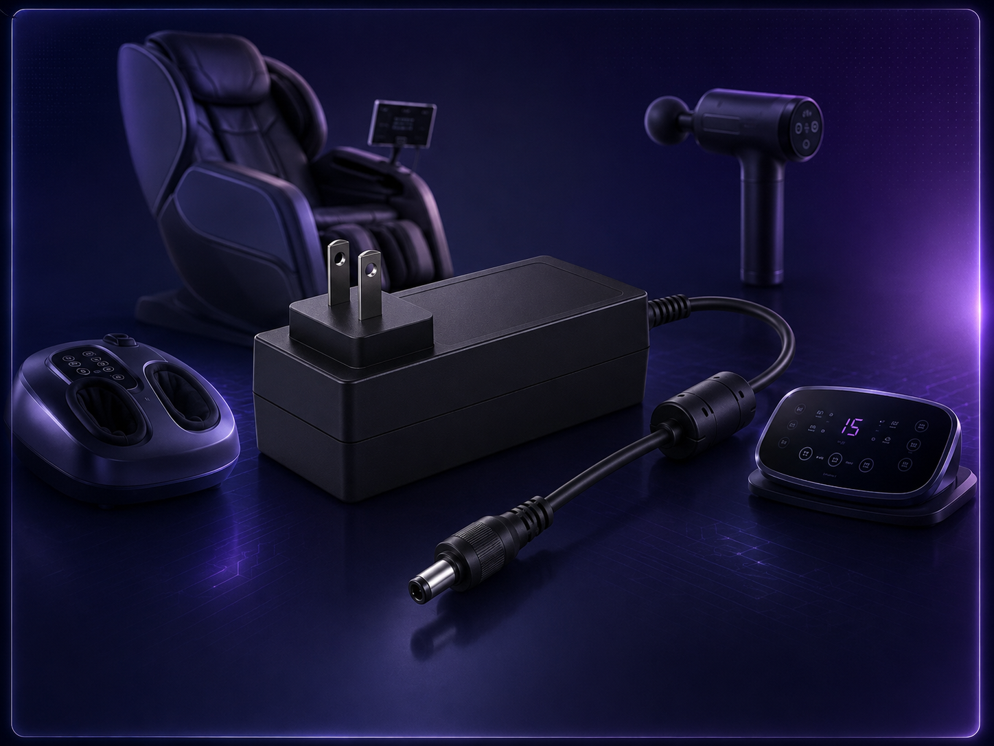
Massage Device Power Adapters
Power solutions for PLC, CNC, servo and automation equipment
📖 Related Guides
✅ Related Certifications
UL 62368-1 Safety Certification
Safety standard covering connector creepage/clearance, temperature rise, and strain relief requirements for IT/AV equipment power adapters.