
1. Introduction: Why Protection Matters
In industrial environments, a power supply failure is never just a component replacement. The cost of an unprotected failure cascades: damaged downstream electronics, corrupted PLC programs, uncontrolled machine motion, production downtime measured in hours or days, and in worst cases, personnel safety incidents.
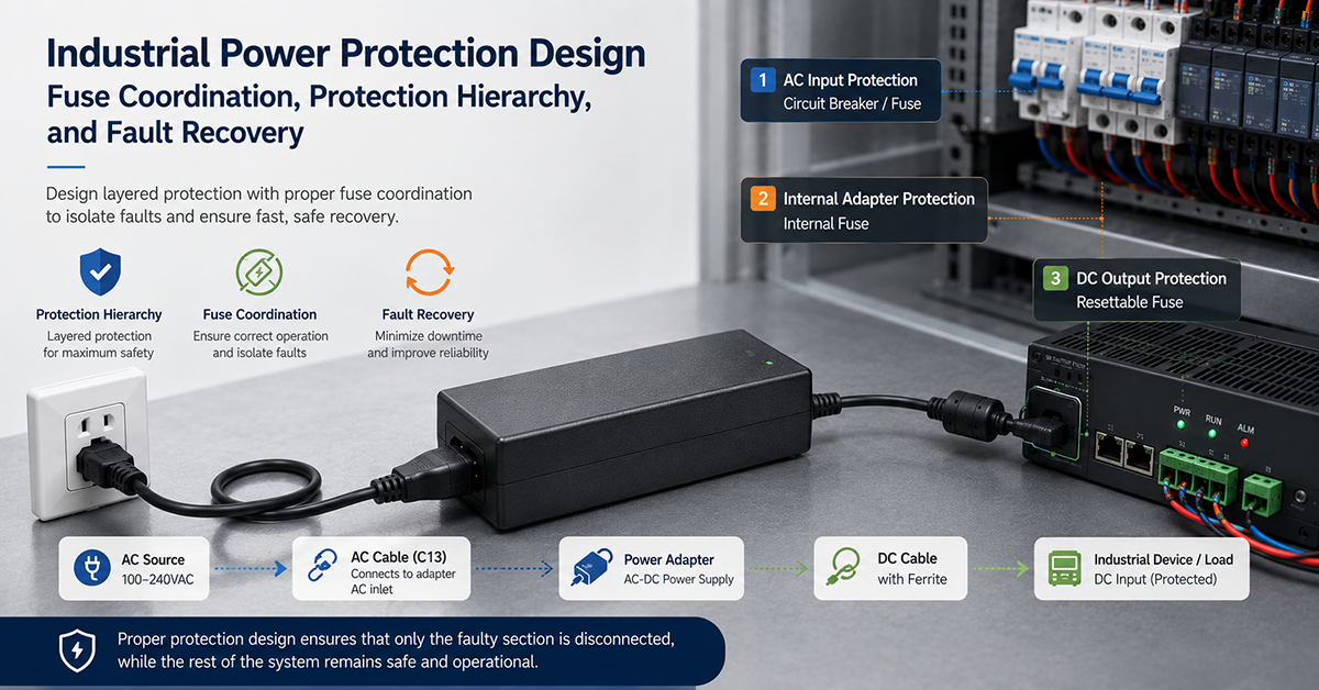
Protection design is the engineering discipline that prevents these outcomes. It’s not about adding components — it’s about designing a coordinated system where the nearest protection device to a fault opens first, the fault is isolated to the smallest possible zone, and the system recovers automatically or reports the failure for intervention.
This article covers the complete protection hierarchy from AC input to individual loads, with design methodology, component selection, and coordination rules. For the foundation of protection features and safety standards, start with Common Power Supply Failure Modes (PF03). For application-specific protection in harsh environments, see Choosing Power Adapters for Harsh Industrial Environments (IA11).
2. Protection Hierarchy — System-Level Approach
A well-designed protection system operates at five levels. Each level handles a specific fault domain and coordinates with the levels above and below.
Level 1 — AC Input Protection
The first line of defense at the mains interface.
- Mains fusing: Overcurrent protection at the building/service level. Typically selected by the panel builder based on total system load.
- Surge protection (SPD): Type 1 (direct lightning, 10/350µs) or Type 2 (induced surge, 8/20µs) protectors at the service entrance or distribution panel.
- Input filtering: EMI/EMC filters that also attenuate line transients. Common mode chokes + X/Y capacitors.
Level 2 — Power Supply Internal Protection
Protection built into the power supply itself.
- OCP (Overcurrent Protection): Limits output current to prevent damage to the supply.
- OVP (Overvoltage Protection): Clamps or shuts down output if internal regulation fails.
- OTP (Overtemperature Protection): Thermal shutdown if internal temperature exceeds safe limits.
- Foldback: Reduces output current under overload to limit internal power dissipation.
- Hiccup: Periodic restart attempts during sustained short-circuit conditions.
Level 3 — DC Bus Protection
Protection on the main DC distribution bus.
- Bus fusing: Main fuse between power supply output and distribution panel. Rating based on total bus capacity.
- DC surge protection: TVS diodes on the DC bus to clamp transients from load switching or external coupling.
- Bus capacitor bank: Hold-up and smoothing capacitors that also absorb transient energy.
Level 4 — Distribution Protection
Protection at the branch level.
- Per-branch fusing: Individual fuses or circuit breakers for each distribution branch.
- eFuse ICs: Integrated protection devices with OCP, OVP, UVLO, and current monitoring.
- PTC resettable fuses: Self-resetting overcurrent protection for moderate-current branches.
Level 5 — Load Protection
Protection at the individual device or circuit level.
- Per-port eFuses: Individual protection for each output port or load connector.
- PTC fuses: Low-cost resettable protection for sensors and low-power loads.
- Load switches: Integrated protection + switching for controlled power delivery.
Key Design Principle
Closest protection to the fault → fastest clearance → minimum disruption.
A short at a sensor should open the sensor’s PTC, not the branch fuse, and certainly not the main bus fuse. This principle — protection coordination — is the difference between a momentary loss of one sensor and a full system shutdown.
3. Overcurrent Protection
Overcurrent is the most common fault in industrial systems. It can result from short circuits, component failures, overload conditions, or incorrect wiring.
Fuse Types
Fuses are the primary overcurrent protection device in most industrial power systems. Each type has distinct time-current characteristics suited to specific loads.
| Fuse Type | Symbol | Characteristic | Best Application |
|---|---|---|---|
| Fast-blow (FF) | FF | Very fast response, low I²t | Semiconductor protection, sensitive electronics |
| Medium-blow (F) | F | Standard fast response | General electronics, power supplies |
| Slow-blow (T) | T | Tolerates temporary inrush | Motor starting, capacitive loads, transformer primaries |
| Time-delay (TT) | TT | Extended inrush tolerance | Heavy inductive loads, welding equipment |
| Ultra-fast (U-F) | U-F | Extremely fast, very low I²t | IGBTs, power semiconductors, rectifier diodes |
Fast-blow (FF): Opens in <1 second at 200% rated current — protects sensitive semiconductors, but may nuisance-blow on moderate inrush.
Slow-blow (T): Delayed by a thermal mass that takes seconds to trip, letting motors and capacitive supplies start without nuisance blowing.
Time-delay (TT): An extension of slow-blow with longer delays, for inrush durations that exceed standard slow-blow tolerance.
Fuse Selection Criteria
| Parameter | Selection Rule | Example |
|---|---|---|
| Current rating | 125–150% of continuous load, 200%+ for loads with high inrush | 5A continuous → 6.3A or 8A fuse |
| Voltage rating | Must exceed maximum system voltage (DC or AC) | 24V system → ≥32V fuse rating |
| Breaking capacity | Must exceed maximum fault current available | 100A fault → ≥100A breaking capacity |
| I²t rating | Must exceed load inrush energy | Motor startup I²t < fuse I²t |
I²t energy: Fuses respond to the integral of current squared over time. For pulsed or inrush currents, the fuse I²t must be higher than the load inrush I²t by a safety margin of 2:1 minimum.
Current Rating Derating
Fuse current ratings assume 25°C ambient. At higher temperatures, the fuse’s effective current-carrying capacity decreases.
| Ambient Temperature | Derating Factor |
|---|---|
| 25°C | 1.00 (nominal) |
| 50°C | 0.90 |
| 70°C | 0.80 |
| 85°C | 0.70 |
Example: A 5A fuse at 70°C ambient effectively carries 5A × 0.80 = 4.0A. Select a fuse rated at 5A ÷ 0.80 = 6.25A — the next standard size is 6.3A.
Fuse Coordination (Selectivity)
Coordination ensures that when a fault occurs, only the fuse nearest the fault opens, leaving upstream fuses intact. This is the foundation of selective fault isolation.
Total selectivity: For all fault currents up to the maximum rated breaking capacity, the downstream fuse opens before the upstream fuse.
Partial selectivity: Selectivity holds up to a certain fault current level. Beyond that, both fuses may operate. Acceptable when fault currents are well-characterized and limited.
Coordination Rules
1.6:1 current ratio rule: For most fuse pairs, a minimum 1.6:1 ratio between upstream and downstream fuse ratings provides total selectivity. For example:
| Downstream Fuse | Minimum Upstream Fuse |
|---|---|
| 1A | 1.6A (next size: 2A) |
| 2A | 3.2A (next size: 4A) |
| 5A | 8A |
| 10A | 16A |
Time-current curve verification: Plot the melting time vs current curves for both fuses. The downstream curve must be entirely below and to the left of the upstream curve. At the maximum fault current, the downstream fuse must clear before the upstream fuse’s minimum melting time.
I²t coordination: Compare let-through I²t at the fault current:
– Downstream fuse let-through I²t < Upstream fuse pre-arcing I²t
– Safety margin: 2:1 minimum
Practical Coordination Example
System: 24V/10A PSU → 5A branch fuse → 2A load fuse → 1.5A load
- Normal operation: Both fuses pass 1.5A continuously
- Fault at load (short circuit): Current rises to ~100A (limited by PSU and wiring impedance)
- Coordination check at 100A:
- 2A fuse melts in ~2ms, clearing time ~5ms, let-through I²t ≈ 50 A²s
- 5A fuse pre-arcing I²t at 100A ≈ 200 A²s
- Ratio: 50 < 200 → selectivity achieved
- Result: 2A fuse opens, 5A fuse remains intact. Load circuit is isolated; other loads on the 5A branch continue operating.
Circuit Breakers vs Fuses
| Aspect | Circuit Breaker | Fuse |
|---|---|---|
| Resettable | ✅ Yes | ❌ No (replace) |
| Response time | Slower (thermal + magnetic) | Faster (direct thermal) |
| Breaking capacity | Lower (6–25kA typical) | Higher (up to 200kA) |
| Coordination ease | More consistent curves | Requires I²t verification |
| Cost per installation | Higher initial | Lower initial, replacement cost |
| Visible status | ✅ Trip indicator | ❌ Requires testing |
| Temperature sensitivity | High (thermal trip) | Moderate (derating required) |
Rule of thumb: Use fuses for primary/bus protection (fast, high breaking capacity). Use breakers for branch protection where resettability reduces downtime.
4. Overvoltage Protection
Overvoltage events damage electronics through dielectric breakdown, oxide puncture, and junction destruction. Industrial environments face two types: transient overvoltage (surges) and sustained overvoltage (regulator failure).
Surge Protective Devices (SPDs)
SPDs divert surge energy to ground, limiting the voltage seen by downstream equipment.
| Type | Waveform | Application | Typical Location |
|---|---|---|---|
| Type 1 | 10/350 µs (direct lightning) | Service entrance, main panel | ≥10kA nominal discharge |
| Type 2 | 8/20 µs (induced surge) | Distribution panels, sub-panels | ≥20kA nominal discharge |
| Type 3 | Combined waveforms | Equipment-level, point-of-use | Integrated or plug-in |
Selection: Use Type 2 at the PSU input for most industrial installations. Add Type 3 at sensitive equipment for critical applications.
MOV (Metal Oxide Varistor)
The most common transient suppression component.
Clamping voltage selection: 1.2–1.5× nominal AC/DC voltage. A 24V DC system should use a MOV with a clamping voltage of approximately 33V–39V.
Energy rating (Joules): Match to the expected surge environment. For industrial control panels, 20J–40J per MOV is typical. Higher energy environments require 50J–100J+.
Failure mode: MOVs degrade with each surge event. End-of-life is a short circuit, which must be protected by a thermal fuse or series fuse to prevent fire.
Selection rule: MOV clamping voltage > maximum system voltage × 1.3. Standby current at nominal voltage < 1mA.
TVS Diodes
TVS diodes respond faster than MOVs and have more precise clamping voltages, but handle less energy.
| Parameter | TVS Diode | MOV |
|---|---|---|
| Response time | <1ns | <25ns |
| Clamping precision | ±5% | ±20% |
| Energy capacity | Lower (up to 6kW peak) | Higher (up to 500J) |
| Lifetime surges | Thousands | Hundreds (degrading) |
| Failure mode | Short (low impedance) | Short (thermal runaway) |
Application on DC rails: TVS diodes are preferred for protecting sensitive electronics on DC buses. Use a unidirectional TVS for positive-referenced DC rails, bidirectional for AC or floating lines.
Combination strategy: MOV + TVS in parallel — the MOV absorbs the bulk surge energy while the TVS provides precise clamping. Place the TVS closer to the load.
Crowbar Circuits
A crowbar circuit deliberately creates a short circuit (through an SCR or TRIAC) when overvoltage is detected, which then opens the upstream fuse or circuit breaker.
Application: Critical loads that require hard shutdown on overvoltage — PLC power inputs, safety controllers, processor modules.
Operating principle: a Zener reference senses overvoltage, triggers the SCR gate above threshold (e.g. 28V on a 24V rail), the SCR shorts the output to ground, and the upstream fuse/breaker opens to isolate the fault.
Reset: Manual only — crowbar circuits latch, so restoring power requires human intervention.
Per-Rail Protection Strategies
| DC Rail | Recommended Protection |
|---|---|
| 24V rail | TVS (30V standoff, 33V clamping) + MOV (39V) |
| 48V rail | TVS (58V standoff, 64V clamping) + Gas discharge tube |
| 12V rail | TVS (15V standoff, 17V clamping) |
| 5V/3.3V rail | Low-voltage TVS + eFuse with OVP |
5. Undervoltage Protection
Undervoltage (brownout) is insidious — loads may not fail immediately but operate marginally, producing random faults, data corruption, or logic errors.
Brownout Detection
AC brownout: Input voltage falls below the minimum operating range. The power supply may continue to deliver output with reduced regulation, or drop out entirely.
DC brownout: The DC bus voltage falls below the minimum threshold for load operation. This can be caused by AC brownout, overload, or capacitor aging.
Detection circuit: A comparator with hysteresis monitors the AC input or DC bus. When voltage falls below threshold, a power-fail warning signal is generated.
UVLO (Undervoltage Lockout)
UVLO prevents the power supply or load from turning on when the input voltage is too low for proper operation. It also prevents partial operation during brownout conditions.
Hysteresis: UVLO includes hysteresis to prevent oscillation at the threshold. Turn-on threshold is higher than turn-off threshold.
| Application | Turn-On | Turn-Off | Hysteresis |
|---|---|---|---|
| 24V load | 20V | 18V | 2V |
| 48V load | 40V | 36V | 4V |
| 12V load | 10V | 9V | 1V |
Hold-Up Time Design
Hold-up time is the duration the power supply can maintain regulated output after AC input is removed. It’s determined by the energy stored in the bulk capacitors.
Formula: C = 2 × P × t_hold / (V²_in_min − V²_in_cutoff)
Where: C = bulk capacitance (Farads), P = output power (Watts), t_hold = required hold-up time (seconds), V_in_min = minimum DC bus voltage, V_in_cutoff = DC bus cutoff voltage
Example: A 120W supply requires 20ms hold-up. Minimum DC bus is 300V, cutoff is 250V.
C = 2 × 120 × 0.020 / (300² − 250²)
C = 4.8 / (90,000 − 62,500)
C = 4.8 / 27,500
C = 175µF
Typical hold-up requirements:
– 10ms (½ cycle of 50Hz) — minimum for line dip
– 20ms (1 cycle) — standard for most industrial applications
– 50ms+ — brownout ride-through for critical systems
Extending hold-up:
– Additional bulk capacitance — simplest but increases inrush
– Hold-up modules — dedicated capacitors with charge/discharge control
– External UPS — for extended ride-through >100ms
Power-Fail Warning
An early warning signal (AC_OK or PFW) that asserts before the output drops out, giving the system time for a controlled shutdown.
Timing: Power-fail warning → t_hold_start → hold-up period → output dropout
The power-fail warning should assert at least 5ms before the output drops below regulation, allowing a microcontroller to save state and prepare for shutdown.
6. Reverse Polarity Protection
Reverse polarity is a common wiring mistake during installation or maintenance. Without protection, it can instantly damage electronics.
Diode-Based (Simple)
A series diode blocks reverse current at the cost of a forward voltage drop.
| Diode Type | Forward Drop | Power Loss at 5A | Application |
|---|---|---|---|
| Standard silicon | 0.7V | 3.5W | Low-cost, low-power |
| Schottky | 0.3V | 1.5W | Medium-power, higher efficiency |
| Ideal diode IC | 0.01V | 0.05W | High-efficiency, high-power |
Limitation: The diode conducts continuously, so power dissipation is proportional to current. At 10A, a standard diode dissipates 7W — requiring a heatsink.
MOSFET-Based (Efficient)
A P-channel MOSFET with the gate pulled to ground via a resistor. On correct polarity, the MOSFET turns on (low Rds(on)). On reverse polarity, the gate-source voltage is zero or negative, and the MOSFET remains off.
Advantages: Power loss = I² × Rds(on). A 10mΩ MOSFET at 5A dissipates only 0.25W — no heatsink required.
Circuit elements:
– P-channel MOSFET (source connected to positive input)
– Gate pull-down resistor (10kΩ–100kΩ)
– Optional Zener diode for gate protection
Comparison
| Method | Drop | Power Loss (5A) | Complexity | Cost |
|---|---|---|---|---|
| Diode | 0.7V | 3.5W | ★ (lowest) | $ |
| Schottky | 0.3V | 1.5W | ★ | $$ |
| P-FET | 0.01–0.05V | 0.05–0.25W | ★★ | $$$ |
| Ideal diode IC | 0.005–0.01V | 0.025–0.05W | ★★★ | $$$$ |
Recommendation: Use Schottky for low-power loads (<2A). Use P-FET for 2A–15A loads. Use ideal diode for high-efficiency or OR-ing applications.
7. Short-Circuit Protection
A short circuit is the hardest fault to protect against — current rises almost instantly to the maximum the supply can deliver, limited only by wiring impedance.
Current Limiting
Constant current limiting: The power supply reduces output voltage to maintain output current at a fixed limit. The downside: at short circuit, the supply dissipates V_out × I_limit in internal heat — potentially destructive for extended durations.
Foldback current limiting: The output current is reduced to a lower value (typically 20–40% of the current limit) during a short circuit. This significantly reduces internal power dissipation.
Foldback ratio: I_sc / I_limit. A ratio of 0.3 means at short circuit, the output current folds back to 30% of the current limit value.
| Protection Mode | Power Dissipation (Short Circuit) | Recovery | Best For |
|---|---|---|---|
| Constant current | Highest (V_out × I_limit) | Automatic when load removed | Linear loads, simple systems |
| Foldback | Moderate (V_out × I_sc) | Automatic, may latch with non-linear loads | Resistive loads, general industrial |
| Hiccup | Very low (pulsed) | Automatic — periodic retry | Capacitive loads, motors |
| Latch-off | None (disabled) | Manual reset only | Critical safety loads |
Hiccup Mode
Hiccup mode is the preferred short-circuit protection for most industrial power supplies.
Operation:
1. Fault detected → output shuts down (disables switching)
2. Wait T_off (typically 32ms–2s) — cooling period
3. Attempt restart — output enabled for T_on (typically 8–32ms)
4. If fault persists → return to step 2 (infinite retry)
5. If fault cleared → resume normal operation
Average power at short circuit: P_avg = (T_on / (T_on + T_off)) × P_short
With T_on = 10ms and T_off = 1s: P_avg = (0.01 / 1.01) × P_short ≈ 1% of short-circuit power.
Advantages: Very low thermal stress, automatic recovery when fault clears, no manual intervention needed.
8. Load Protection
Per-Port Protection
In distributed systems, protecting individual output ports prevents a single device fault from affecting other loads on the same supply.
eFuse ICs combine multiple protection functions in one small package: programmable OCP (±10%), OVP, UVLO, thermal shutdown, reverse-current blocking, and monitoring (current-sense output, fault flag, enable/disable).
Popular applications: Per-port protection on PLC output modules, peripheral power on HMIs, USB power ports, and distributed I/O nodes.
PTC Resettable Fuses
PTCs increase resistance dramatically when their rated current is exceeded, then return to low resistance when the fault is removed and power is cycled.
| Parameter | Description |
|---|---|
| Hold current (I_hold) | Maximum continuous current without tripping |
| Trip current (I_trip) | Current at which the PTC switches to high resistance (~2× I_hold) |
| Time to trip | Seconds to minutes depending on fault current |
| Operating temperature range | Typically -40°C to +85°C |
| Temperature derating | Hold current decreases ~1%/°C above 25°C |
Temperature derating example: A 1.0A PTC at 25°C has I_hold = 1.0A. At 60°C, I_hold = 1.0A × 0.80 = 0.80A. For reliable operation at 60°C, select a PTC with I_hold (specified at 25°C) of at least 1.0A / 0.80 = 1.25A.
Best use: Low-cost per-port protection for sensors (proximity, photoelectric), low-power actuators, and non-critical loads.
9. Fault Recovery Strategies
The recovery strategy determines how a system behaves after a fault is cleared. The right choice depends on the application’s fault tolerance and safety requirements.
Auto-Recovery (Hiccup Mode)
Behavior: After a fault is detected, the supply retries automatically at fixed intervals. When the fault clears, normal operation resumes.
Best for: Transient faults — temporary overloads, capacitive charging, brief short circuits.
Limitations: Unlimited retries can cause system instability if a permanent fault causes repeated power cycling of downstream loads. Some loads (motors, solenoids) may be damaged by repeated start/stop cycles.
Latch-Off (Manual Reset)
Behavior: On fault detection, the supply shuts down and remains off until manually reset (power cycle or remote reset signal).
Best for: Sustained faults — short circuits, component failures, environmental overloads.
Limitations: Requires human intervention to restore power. May cause extended downtime for minor transient faults.
Hybrid Approach
Behavior: Auto-recovery for the first N attempts (e.g., 3 retries), then latch-off. Combines the benefits of both approaches.
Best for: Systems with a mix of transient and permanent fault risks — most industrial automation systems.
Timing parameters:
– Retry attempts: 3 (configurable 1–10)
– Retry interval: 1 second
– After 3rd failure: Latch-off with fault indicator
Fault Logging
Modern protection ICs can log fault events for predictive maintenance and failure analysis.
What to log:
– Fault type (overcurrent, overvoltage, overtemperature)
– Fault duration
– Fault count (number of occurrences)
– Ambient conditions (temperature, input voltage at time of fault)
– Timestamp for correlation with production events
Storage methods:
– EEPROM in the power supply module
– Flash memory in the host system
– Cloud logging via IoT gateway
Application: Trending fault frequency helps identify developing problems before they cause downtime. A gradual increase in overtemperature events, for example, may indicate a failing fan or dust-clogged heatsink.
Remote Reset
For systems in inaccessible locations (machines, remote panels), remote reset capability reduces maintenance visits.
Remote reset methods:
– Digital input (dry contact or 24V signal)
– I²C/SMBus command through protection IC
– Network-based reset (Modbus, Ethernet/IP, Profinet)
10. Protection Coordination — Cascade Analysis
Coordination analysis ensures the entire protection chain operates correctly — that the closest fuse to a fault opens before upstream devices, and that no single fault disables more of the system than necessary.
Coordination Steps
Step 1: Map the protection chain
Document every protection device from the mains to the final load.
Mains (50A breaker)

→ PSU input (10A fuse)

→ PSU output (internal OCP at 11A)

→ DC bus (10A fuse)

→ Branch 1 (5A fuse)

→ Load 1.1 (2A fuse → device)

→ Load 1.2 (1A PTC → sensor)

→ Branch 2 (5A CB)

→ Load 2.1 (3A fuse → actuator)
Step 2: Identify upstream/downstream pairs
For each device, identify the next device closer to the source (upstream) and the next device closer to the load (downstream).
Step 3: Plot time-current curves
Overlay the operating curves for each upstream/downstream pair. Verify that the downstream curve is entirely below and to the left of the upstream curve.
Step 4: Verify I²t coordination
For fuses: Downstream let-through I²t < upstream pre-arcing I²t. Safety margin: 2:1.
Coordination Challenges
High fault currents: At very high fault currents (>10× rated), the time gap between upstream and downstream fuse operation narrows. Both fuses may operate nearly simultaneously.
Cumulative I²t: Multiple downstream faults in rapid succession can cumulatively heat the upstream fuse, causing it to open even though each individual fault was within coordination limits.
Solutions:
– Use current-limiting fuses — they reduce the let-through energy at high fault currents
– Increase the ratio between upstream and downstream ratings (2:1 vs 1.6:1)
– Add series impedance (small resistor or inductor) to reduce fault current
– Use circuit breakers with adjustable time-delay characteristics
11. Recommended YHYadapter Products
| Model | Power | Protection Features | Best Application |
|---|---|---|---|
| YHY-24002500 | 60W/2.5A | OCP, OVP, SCP | Small automation, sensor networks |
| YHY-24005000 | 120W/5A | OCP, OVP, SCP | PLC systems, HMI, mid-range automation |
| Available by model | 240W/10A | Confirm protection feature set with engineering | Large systems, multi-branch distribution |
| Custom OEM | Per spec | eFuse per port, remote reset, fault logging configurable (confirm with engineering) | OEM critical systems |
Protection features are model-specific and confirmed per model at specification. Per-port eFuse protection, remote reset, and fault logging are available as OEM customization options — confirm feasibility, configuration, and applicable certification with engineering for your specific program.
Protection Feature Comparison
| Feature | YHY-24002500 | YHY-24005000 | Available by model (240W+) |
|---|---|---|---|
| Overcurrent protection | ✅ | ✅ | ✅ |
| Overvoltage protection | ✅ | ✅ | ✅ |
| Short-circuit protection | ✅ | ✅ | ✅ |
| Thermal shutdown | ✅ | ✅ | ✅ |
| Foldback / fault flag / remote reset | Confirm by model | Confirm by model | Confirm by model |
Protection feature availability (including OCP, OVP, SCP, and thermal shutdown) is confirmed per model against the model datasheet and specification.
12. Frequently Asked Questions
Which protection mode is best for short circuits?
For most industrial supplies, hiccup mode gives the lowest thermal stress with automatic recovery: the output shuts down, retries periodically, and resumes when the fault clears. Foldback suits resistive loads; latch-off suits critical loads that require manual intervention.
What fuse ratio provides selectivity between upstream and downstream fuses?
A minimum 1.6:1 current ratio between upstream and downstream fuse ratings provides total selectivity for most fuse pairs, supported by I²t verification: let-through I²t of the downstream fuse must be lower than the upstream fuse pre-arcing I²t by at least 2:1.
How is hold-up time capacitance calculated?
C = 2 × P × t_hold / (V²_in_min − V²_in_cutoff), where P is output power, t_hold the required hold-up time, and V_in_min / V_in_cutoff the DC bus voltage limits. A 120W supply with 20ms hold-up, a 300V minimum bus and a 250V cutoff needs approximately 175µF.
Are protection features standard on all YHYadapter industrial models?
Protection features are model-specific. OCP/OVP/SCP configurations and options such as per-port eFuse, remote reset, and fault logging are confirmed per model against the datasheet and specification — confirm with engineering for your program.
Do 24V and 48V rails need different protection components?
Yes. Rail voltage sets the standoff and clamping values — a 24V rail typically uses a TVS with ~30V standoff and ~33V clamping plus a MOV, while a 48V rail requires higher-standoff devices (TVS ~58V standoff) and can use a gas discharge tube. See the per-rail strategy table in Section 4.
13. Related Resources
- PF03 — Common Power Supply Failure Modes — Foundation protection knowledge
- IA11 — Choosing Power Adapters for Harsh Industrial Environments — Protection in extreme conditions
- IA01 — How to Choose the Right Power Adapter for Your Industrial Application — Cluster gateway with protection considerations
- IA12 — Power Supply for PLC Systems — Enable link after IA12 is live
- IA06 — 24V Industrial Power Supply Selection Guide — Enable link after IA06 is live
- Certifications Hub — /certifications/ — Safety and compliance references
- Industrial Application Hub — /industrial-control-power-solutions/
CTA: Discuss Your Protection Design Requirements | Browse Power Adapters | Request Custom Protection Configuration