
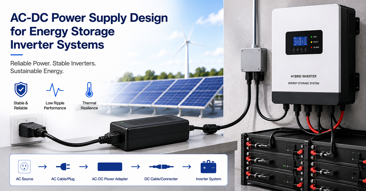
Energy storage inverters—whether standalone battery inverters, hybrid solar-plus-storage inverters, or bidirectional inverter-chargers—require multiple internal power supply stages to operate correctly. The main power stage converts DC battery voltage to AC output (and vice versa for bidirectional units). The auxiliary power supply provides regulated low-voltage power for the control board, gate drivers, communication interfaces, and cooling fans. The gate drive power supplies must provide isolated voltages for the inverter’s high-side and low-side switching devices.
This guide covers the AC-DC and DC-DC power supply design considerations for energy storage inverter systems: auxiliary power supply architecture, gate drive power requirements, thermal management, and OEM design considerations.
Auxiliary Power Supply Architecture
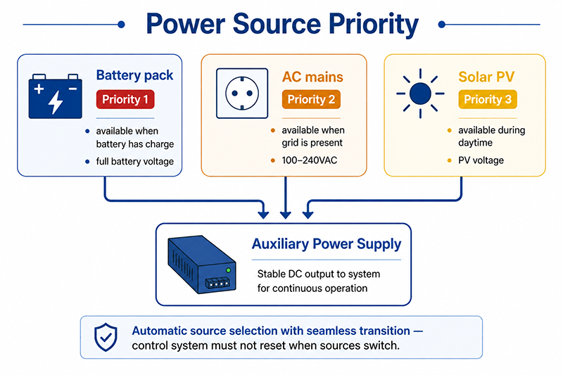
The auxiliary power supply is the “housekeeping” power supply that keeps the inverter’s control electronics operational. It must function whenever the system has power available—from the battery, from AC mains, or from solar (in hybrid inverters)—and must transition seamlessly between power sources.
Power Source Prioritization
| Power Source | When Available | Priority | Typical Voltage | Notes |
|---|---|---|---|---|
| Battery pack | Always (if battery has charge) | 1 | Full battery voltage | Primary source during battery-powered operation |
| AC mains | When grid is present | 2 | 100–240VAC | Used when grid is available and battery is low |
| Solar (PV input) | During daytime | 3 | PV voltage | Used when solar is generating and battery is discharged |
Auxiliary Power Supply Stages
| Output Voltage | Typical Current | Purpose |
|---|---|---|
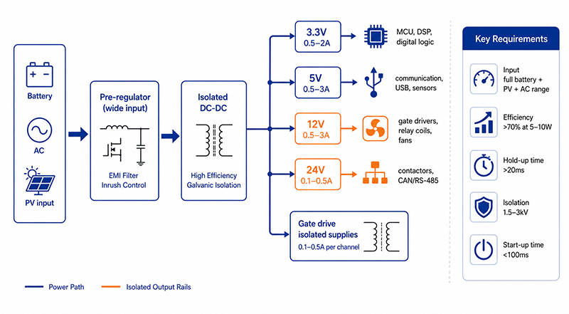
| 3.3V | 0.5–2A | MCU, DSP, digital logic |
| 5V | 0.5–3A | Communication interfaces, USB, auxiliary sensors |
| 12V | 0.5–3A | Gate drivers, relay coils, cooling fans |
| 24V | 0.1–0.5A | Contactors, external communication (CAN, RS-485) |
| Isolated (gate drive) | 0.1–0.5A per channel | High-side and low-side gate drive |
Auxiliary Power Supply Requirements
| Parameter | Typical Requirement | Notes |
|---|---|---|
| Input voltage range | Full battery voltage + PV + AC | 12V–60V typical for battery input; 100–240VAC for AC input |
| Efficiency at low load | >70% at 5–10W | Inverter housekeeping load is typically 5–20W |
| Hold-up time | >20ms at full load | Maintain operation through AC mains dropout |
| Isolation | 1.5–3kV reinforced | Safety isolation for user-accessible circuits |
| Start-up time | <100ms from power-up | Inverter must be operational quickly when power is applied |
Why This Matters
- The auxiliary power supply is always on when the system has power. Its efficiency at low load (5–20W) determines the system’s housekeeping consumption, which subtracts from the battery’s usable capacity.
- An inverter consuming 10W for housekeeping from a 10kWh battery loses 2.4% of capacity per day to housekeeping alone. Reducing housekeeping power to 5W cuts this to 1.2%.
- The auxiliary supply must operate across the full battery voltage range, from depletion voltage (e.g., 42V for a 48V LiFePO4) to full charge voltage (58.4V), plus overvoltage tolerance during charging.
OEM Actions
- Calculate the inverter’s total housekeeping power requirement including all subsystems. Select an auxiliary power supply with high efficiency at the expected housekeeping load.
- Design the auxiliary supply to accept input from the battery, AC mains, and solar (in hybrid inverters) with automatic source selection and seamless transition.
- Verify the auxiliary supply’s start-up time from all power sources. The inverter’s control system should be operational within 100ms of power being applied.
Gate Drive Power Supply
The gate drive power supply provides isolated voltage to drive the inverter’s power switches (MOSFETs or IGBTs). In a full-bridge or three-phase inverter topology, the high-side switches operate at different voltage potentials and require isolated gate drive supplies.
Gate Drive Voltage Requirements
| Power Switch Type | Typical Gate Voltage | Gate Power per Switch (at switching frequency) |
|---|---|---|
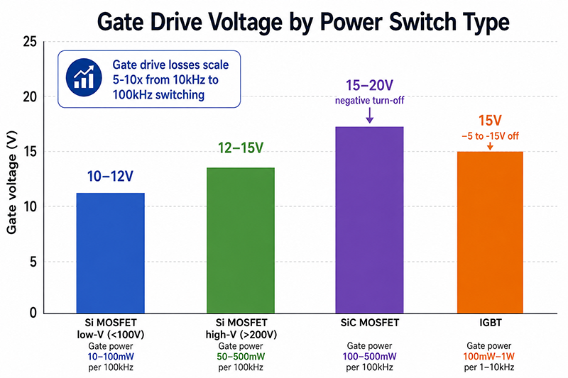
| Si MOSFET (low voltage, <100V) | 10–12V | 10–100mW (per 100kHz switching) |
| Si MOSFET (high voltage, >200V) | 12–15V | 50–500mW (per 100kHz switching) |
| SiC MOSFET | 15–20V (negative turn-off) | 100–500mW (per 100kHz switching) |
| IGBT | 15V on, −5 to −15V off | 100mW–1W (per 1–10kHz switching) |
Gate Drive Power Supply Topologies
| Topology | Best For | Typical Power | Isolation |
|---|---|---|---|
| Push-pull transformer | Low power, multiple outputs | 1–10W total | Transformer |
| Flyback with multiple windings | Medium power, multiple outputs | 5–25W total | Transformer |
| Bootstrap (high-side only) | Low power, low-side reference | 0.1–1W per channel | Capacitive (limited) |
| Dedicated isolated DC-DC module | Per-switch isolation | 1–2W per module | Integrated transformer |
Bootstrap Gate Drive
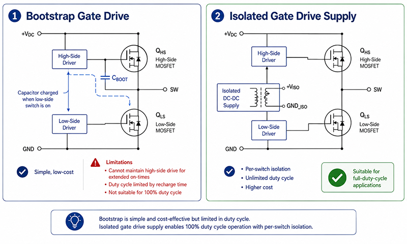
Bootstrap gate drive is commonly used in half-bridge and full-bridge inverter topologies where the low-side switch provides a reference for the high-side gate drive. The bootstrap capacitor is charged when the low-side switch is on, and provides gate charge for the high-side switch when it turns on. The bootstrap technique is simple and low-cost but has limitations:
- Cannot maintain high-side drive for extended on-times (capacitor discharges)
- Duty cycle is limited by bootstrap capacitor recharge time
- Not suitable for 100% duty cycle operation
Why This Matters
- Insufficient gate drive voltage causes the power switches to operate with higher on-resistance (Rds(on)), increasing conduction losses and heating the switches.
- Gate drive power increases with switching frequency. A 100kHz inverter has 5–10× the gate drive losses of a 10kHz inverter.
- Bootstrap gate drive is simple but limits the inverter’s duty cycle range. For inverters requiring 0–100% duty cycle or extended high-side on-times, dedicated isolated gate drive supplies are required.
OEM Actions
- Calculate the total gate drive power requirement based on the number of switches, gate charge, and switching frequency. Include margin for the gate driver IC’s own consumption.
- Select the gate drive power supply topology based on the inverter’s duty cycle requirements, switching frequency, and isolation requirements.
- Verify the gate drive voltage at the switch’s gate terminal under worst-case conditions (low input voltage, maximum load). Measure with an oscilloscope to confirm the gate voltage is within the switch’s specification.
AC-DC Bidirectional Power Stage Design
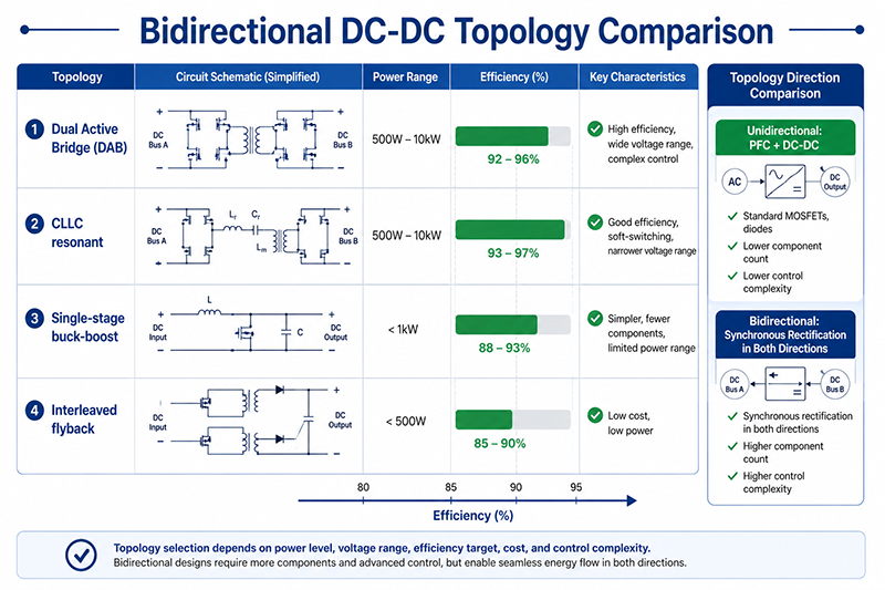
For hybrid inverters that can both charge the battery from AC mains and discharge the battery to AC loads, the power stage must operate bidirectionally. The power stage design considerations differ from unidirectional chargers.
| Parameter | Unidirectional Charger | Bidirectional Inverter-Charger |
|---|---|---|
| Power flow | AC → DC only | AC ↔ DC (both directions) |
| Topology | PFC + DC-DC (LLC/PSFB) | Dual-active bridge + DC-DC or single-stage |
| Control complexity | Moderate | Higher (dual direction control) |
| Efficiency | 90–96% (one direction) | 90–95% (each direction) |
| Components | Standard MOSFETs, diodes | MOSFETs with synchronous rectification in both directions |
| Galvanic isolation | Required | Required (typically high-frequency transformer) |
Topology Comparison for Bidirectional Power
| Topology | Power Range | Typical Efficiency | Notes |
|---|---|---|---|
| Dual active bridge (DAB) | 500W–10kW | 92–96% | High efficiency, wide voltage range, complex control |
| CLLC resonant | 500W–10kW | 93–97% | Good efficiency, soft-switching, narrower voltage range |
| Single-stage (buck-boost) | <1kW | 88–93% | Simpler, fewer components, limited power range |
| Interleaved flyback | <500W | 85–90% | Low cost, low power |
Why This Matters
- Bidirectional operation requires MOSFETs with synchronous rectification in both directions, increasing component count and cost compared to unidirectional designs.
- The control algorithm must handle both charging and discharging modes with seamless transition, including when the inverter switches from grid-tied to off-grid operation.
- The transformer design for bidirectional converters must accommodate power flow in both directions, affecting the magnetizing inductance and leakage inductance optimization.
OEM Actions
- Select the bidirectional power stage topology based on the power range, voltage ratio, and efficiency targets. DAB and CLLC are the most common for ESS applications above 1kW.
- Verify the bidirectional converter’s efficiency in both charging and discharging directions. The efficiency may differ between modes due to different operating conditions.
- Include seamless transition between grid-tied and off-grid modes in the control system design. The power stage must handle the transition without voltage or current transients that could damage the inverter or connected loads.
Useful Links
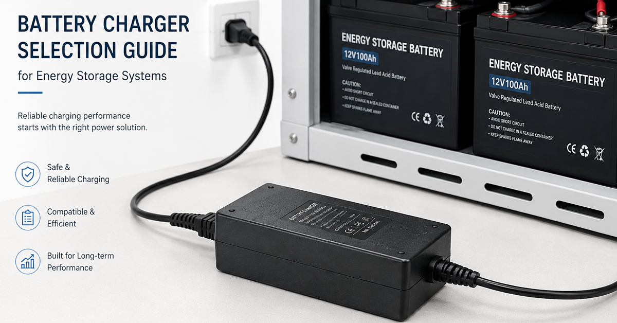
Related article: Battery Charger Selection Guide →
Related article: Power Adapter for Portable Power Stations →
Q: Does an energy storage inverter need a separate auxiliary power supply from the battery charger?
A: In a typical ESS, the auxiliary power supply is integrated into the inverter and powered from the battery. It operates whenever the battery has charge. An AC-powered auxiliary supply provides backup housekeeping power when the battery is depleted and AC mains is available for charging.
Q: What is the typical housekeeping power consumption of an ESS inverter?
A: A typical ESS inverter consumes 5–20W for housekeeping functions: control board (3–5W), gate drives (1–5W), cooling fans (1–10W), and communication interfaces (1–3W). Higher-power inverters and those with active cooling tend toward the higher end of this range.
Q: What happens to the gate drive power when the inverter’s DC bus voltage is low?
A: The gate drive power supply should regulate its output voltage independently of the DC bus voltage. A well-designed gate drive supply will maintain the required gate voltage (±5%) across the inverter’s full operating voltage range. If the gate drive voltage drops, the power switches may operate with higher losses or fail to turn on fully.
Conclusion
Energy storage inverter systems require carefully designed internal power supplies for auxiliary housekeeping, gate drive, and bidirectional AC-DC power conversion. The auxiliary supply must operate from the battery, AC mains, or solar input with automatic source selection. The gate drive supply must provide isolated, regulated voltages for high-side and low-side power switches. The bidirectional power stage in hybrid inverters requires topologies (DAB, CLLC) that support efficient power flow in both directions. Each of these power supply subsystems must be designed for the full operating voltage range, isolation requirements, and thermal constraints of the inverter system.
Related Resources
🔌 Related Products
🏭 Related Applications
Industrial Control Power Solutions
Power solutions for PLC, CNC, servo and automation equipment
📖 Related Guides
Portable Power Stations Solutions
Power adapters for portable stations and backup batteries
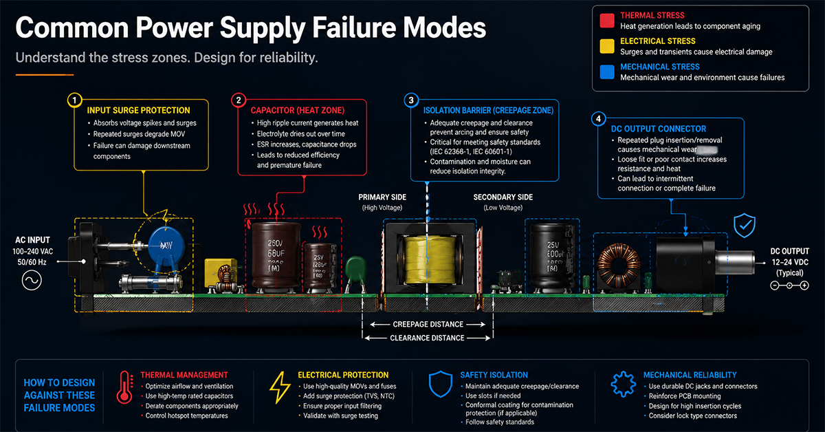
Common Power Supply Failure Modes
Common power supply failure modes and design countermeasures
✅ Related Certifications
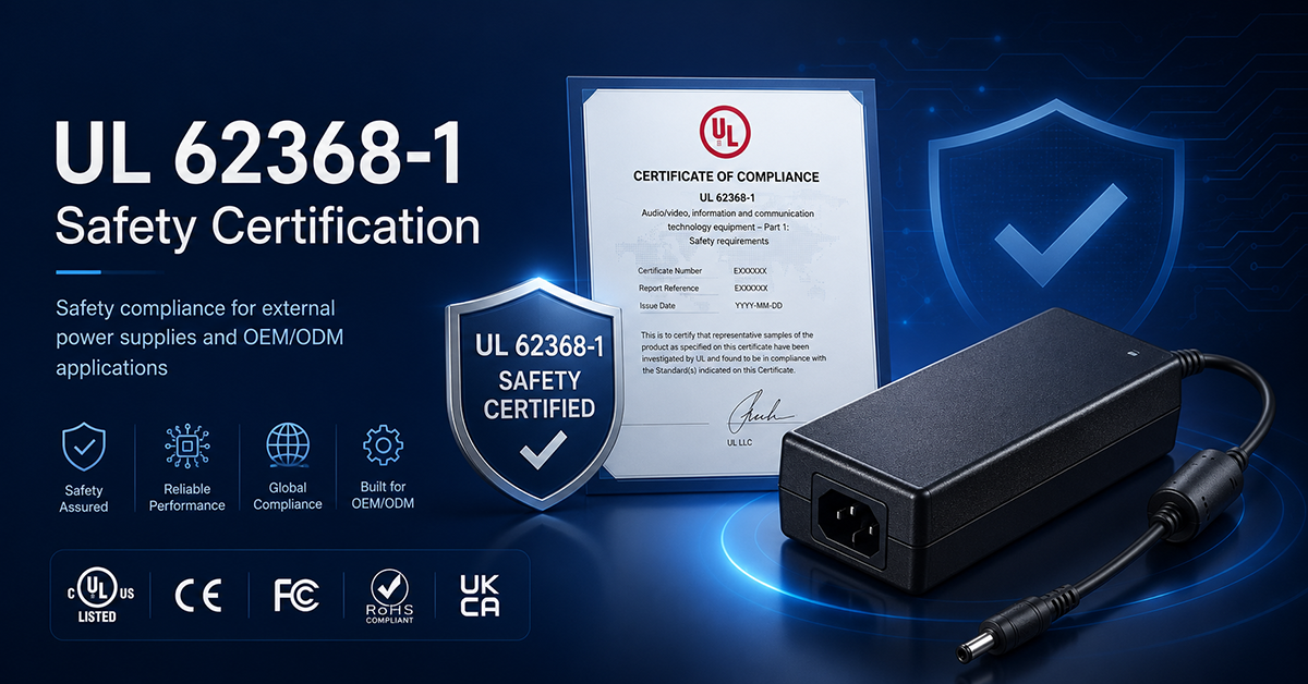
UL 62368-1 Safety Certification
Safety standard covering connector creepage/clearance, temperature rise, and strain relief requirements for IT/AV equipment power adapters.