
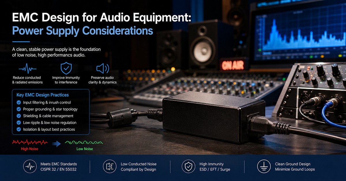
Electromagnetic compatibility (EMC) is one of the most challenging compliance areas for audio equipment because the product both emits and is susceptible to electromagnetic energy. The external power adapter is simultaneously a potential noise source and a potential entry point for interference into the audio device. When the adapter, DC cable, and audio product are combined, the EMC behavior of the system can differ significantly from the adapter tested alone.
This guide covers the EMC design considerations specific to audio equipment using external AC/DC power adapters: conducted and radiated emissions mechanisms, the role of the DC cable, filtering and shielding strategies, grounding architecture effects, and practical pre-compliance testing approaches.
EMC Standards for Audio Equipment
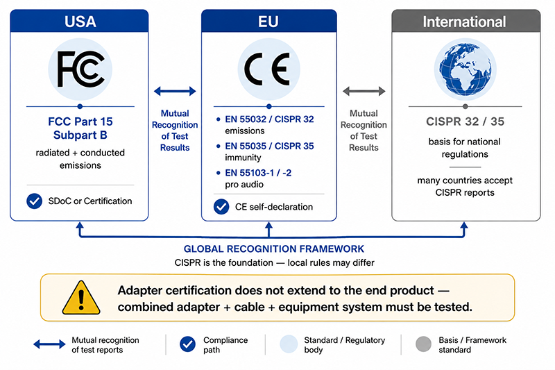
Audio equipment sold in global markets must comply with applicable EMC standards. The relevant standards depend on the equipment’s classification, the markets it will be sold in, and whether it contains digital circuitry.
| Market | Standard | Scope | Applicability |
|---|---|---|---|
| USA | FCC Part 15 Subpart B | Radiated and conducted emissions | All digital electronic products. Audio equipment with any digital circuitry (DSP, USB, Bluetooth, digital amplifier) falls under this requirement. |
| EU | EN 55032 / CISPR 32 | Radiated and conducted emissions | Multimedia equipment emissions. Applies to audio products with digital functions. |
| EU | EN 55035 / CISPR 35 | Immunity | Multimedia equipment immunity to electromagnetic disturbances. |
| EU | EN 55103-1 / -2 | Emissions and immunity | Professional audio and video equipment (older standard, still referenced in some applications). |
| International | CISPR 32 / 35 | Emissions and immunity | Basis for many national regulations. |
The applicability of these standards depends on the equipment’s function, power rating, and target market. Verify the specific requirements against the applicable standard edition and product classification for each target market.
EMC Compliance Paths
| Market | Typical Compliance Approach | Notes |
|---|---|---|
| USA | Supplier’s Declaration of Conformity (SDoC) or Certification | Most audio equipment uses SDoC. Testing to FCC Part 15 is performed by the manufacturer or a third-party lab. |
| EU | CE marking via self-declaration | The manufacturer declares conformity to applicable standards (EN 55032, EN 55035). Technical documentation must be maintained. |
| Other markets | Varies by country | Many countries accept CISPR-based test reports or have mutual recognition agreements. |
Why This Matters
- The power adapter’s conducted and radiated emissions contribute to the total product emissions. An adapter that marginally passes emissions limits when tested alone may cause the combined system to fail when connected to the audio equipment.
- Audio equipment with wireless connectivity (Bluetooth, Wi-Fi, wireless microphone receivers) must also comply with radio standards (FCC Part 15C for intentional radiators, RED for EU), adding another layer of compliance testing.
- EMC compliance is a system-level requirement. The adapter’s certification does not extend to the end product—the combined adapter + cable + equipment system must be tested.
What OEMs Should Do Now
- Identify the EMC standards that apply to your audio product in each target market. Consider both emissions and immunity requirements.
- Request conducted and radiated emissions data for candidate adapters, measured per FCC Part 15 and CISPR 32. Confirm the adapter has adequate margin below the applicable limit.
- Plan for pre-compliance testing of the complete system (adapter + cable + product) early in the design cycle, not after the first production prototype.
The DC Cable — A Critical EMC Element
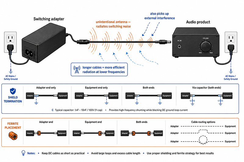
In audio equipment with external power adapters, the DC cable connecting the adapter to the product is often the dominant EMC factor. The cable can act as an unintentional antenna, radiating switching noise from the adapter and also picking up external interference that couples into the audio circuit.
Cable effects on EMC performance
| Factor | Effect | Design Consideration |
|---|---|---|
| Cable length | Longer cables increase radiation efficiency at lower frequencies | Keep cable as short as practical for the installation |
| Cable shielding | Shielded cables can reduce radiated emissions and improve immunity | Shield effectiveness depends on termination strategy, cable type, and grounding architecture |
| Cable routing | Cable proximity to other cables affects coupling | Route DC cable away from audio input cables; avoid parallel runs |
| Ferrite cores | Common-mode suppression | Ferrite at the adapter end, the equipment end, or both depending on system behavior |
| Connector quality | Poor connector grounding or shielding can negate cable improvements | Use connectors with integral shielding and reliable ground contact |
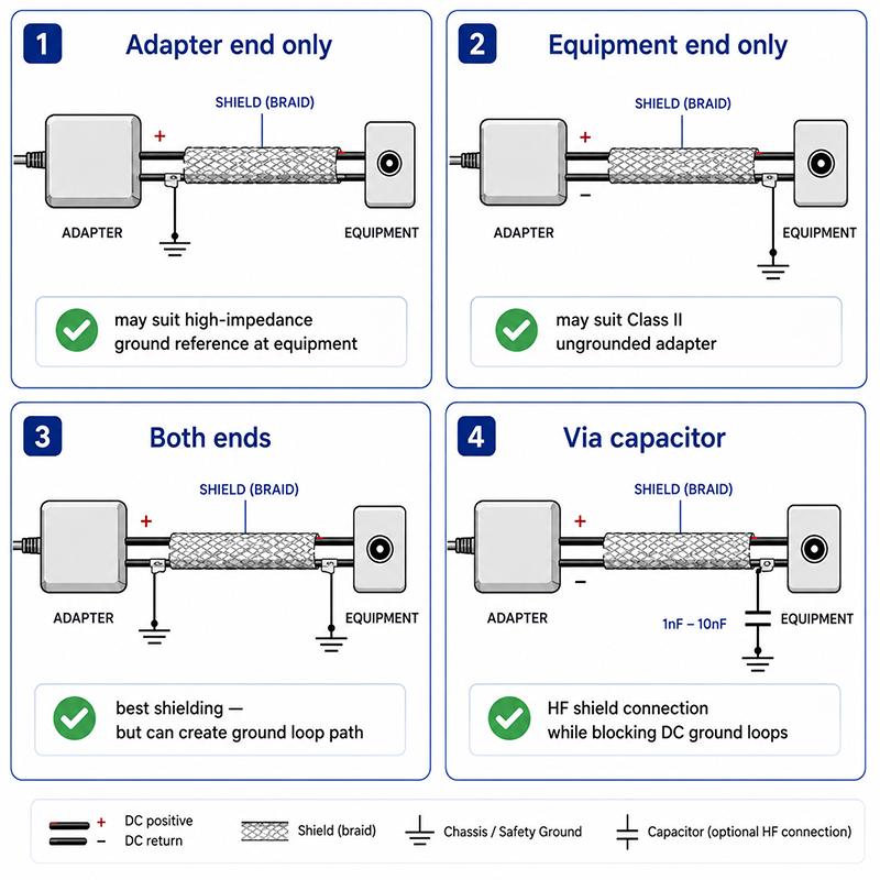
Cable shielding considerations
- Shield grounded at adapter end only: May be effective if the audio equipment has a high-impedance ground reference. Prevents shield current from flowing through the audio equipment ground.
- Shield grounded at equipment end only: May be effective if the adapter is Class II (ungrounded). The equipment chassis provides the ground reference for the shield.
- Shield grounded at both ends: Provides best shielding against external fields but can create ground loop paths through the shield.
- Shield grounded via capacitor: Allows high-frequency shield connection while blocking DC ground loops. Requires careful capacitor selection for the frequency range of concern.
Why This Matters
- A 1m unshielded DC cable connecting a switching adapter to an audio product can radiate sufficient noise to cause the combined product to fail FCC Class B radiated emissions limits, even if the adapter alone passes.
- Adding a ferrite core to the DC cable can reduce radiated emissions by controlling common-mode current, but the optimal placement and core material depend on the noise frequency spectrum.
- The cable’s shield termination strategy affects both radiated emissions and immunity. A shield grounded at both ends provides the best shielding but may introduce ground loop hum.
What OEMs Should Do Now
- Evaluate the DC cable as part of the EMC design, not as a passive component. Test the complete adapter + cable + product configuration during pre-compliance.
- If using a shielded DC cable, determine the shield termination strategy through system-level EMC testing rather than applying a universal rule.
- Consider adding a ferrite core location in the product design (ferrite can be added inside the product enclosure or on the cable near the entry point) as a potential mitigation if needed.
Power Supply Filtering and Its Effect on EMC
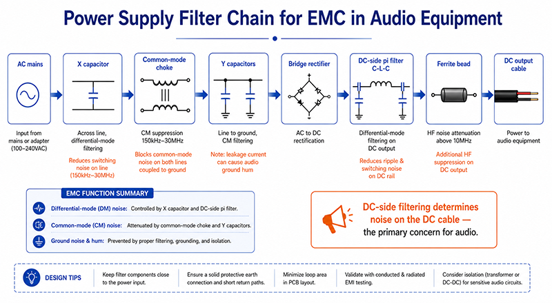
The power supply filtering stage affects both the adapter’s conducted emissions and the audio equipment’s susceptibility to power-line noise. Key filtering components and their roles:
| Component | Function | EMC Impact |
|---|---|---|
| X capacitors (across AC line) | Differential-mode noise filtering | Reduces conducted emissions on AC mains |
| Y capacitors (line to ground) | Common-mode noise filtering | Reduces common-mode conducted emissions; leakage current must be considered for medical/audio equipment |
| Common-mode choke | Common-mode noise suppression | Effective for reducing conducted emissions in the 150kHz–30MHz range |
| DC-side pi filter (C-L-C) | Differential-mode noise on DC output | Reduces conducted noise exiting the adapter on the DC cable |
| Ferrite bead on DC output | High-frequency noise suppression | Attenuates switching noise above 10MHz |
Adapter designs with integrated line filters (common-mode choke + X/Y capacitors) may offer better conducted EMC performance. However, the measured performance on the adapter’s AC input port does not predict the noise present on the DC output cable, which is the primary concern for audio equipment.
Why This Matters
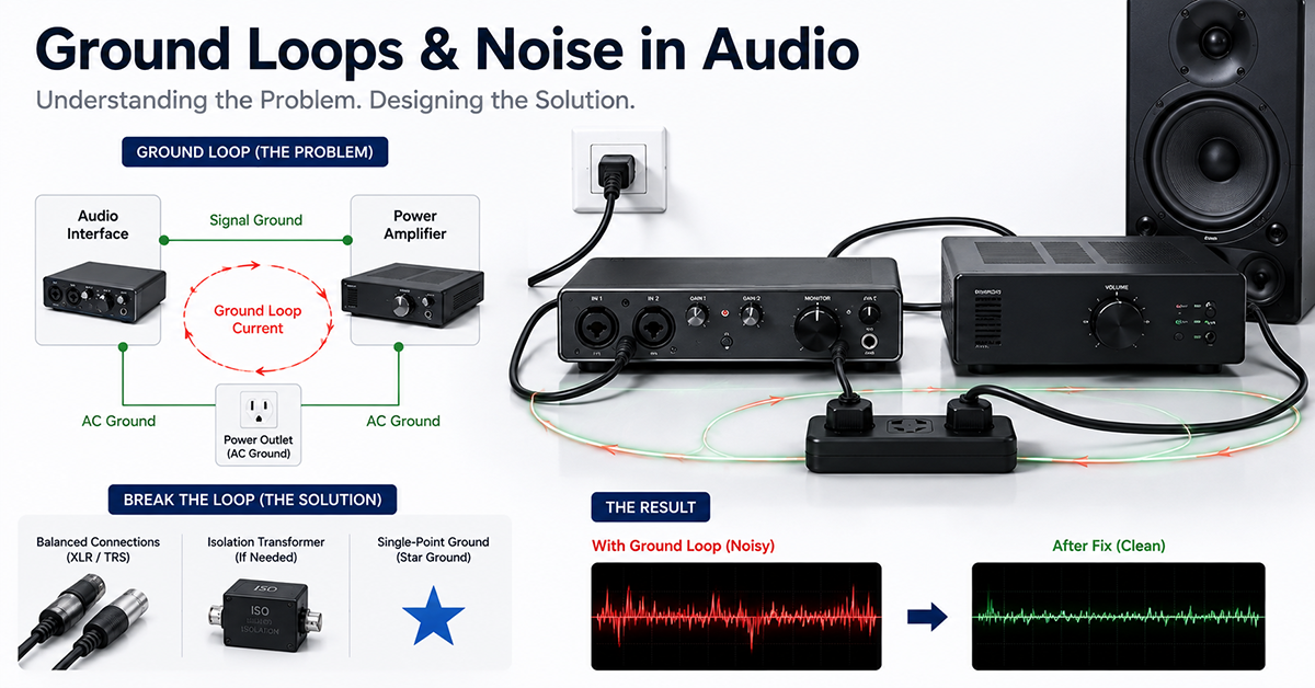
- Y capacitors between AC line and ground create a leakage current path that can contribute to audible hum in audio equipment with a grounded chassis. The adapter’s Y capacitor value affects the amount of mains-frequency current flowing through the ground connection.
- The DC-side filtering of the adapter determines the noise that exits on the DC cable. An adapter with good AC-side filtering but poor DC-side filtering may pass conducted emissions testing but still cause audio noise problems.
- Adding additional filtering at the audio equipment’s DC input (e.g., a ferrite bead or pi filter on the input PCB) can reduce noise entering the equipment from the DC cable, but this adds cost and PCB space.
What OEMs Should Do Now
- Request data on both AC-side and DC-side filtering for candidate adapters. An adapter with LC filtering on the DC output is generally preferred for audio applications.
- Evaluate whether additional filtering at the audio equipment DC input is necessary based on pre-compliance testing results.
- For equipment with a grounded chassis, consider the leakage current path through the adapter’s Y capacitors and its effect on ground loop hum.
Pre-Compliance Testing Approach
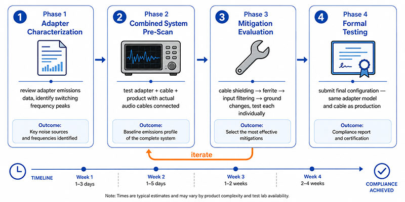
Pre-compliance EMC testing during product development is significantly more cost-effective than discovering EMC issues during formal certification testing. For audio equipment with external power adapters, the following approach is recommended:
Phase 1 — Adapter Characterization
- Review the adapter’s conducted and radiated emissions data from the manufacturer
- Identify any narrowband peaks related to the adapter’s switching frequency and harmonics
- Confirm the adapter has adequate margin below the applicable limit when tested standalone
Phase 2 — Combined System Pre-Scan
- Test the adapter + cable + product in the expected operating configuration
- Identify new emissions that appear only when the adapter is connected to the product
- Evaluate the effect of DC cable length, routing, and shielding
- Test with the actual audio cables connected (input and output)
Phase 3 — Mitigation Evaluation
- If emissions exceed limits, evaluate mitigation in order: cable shielding, ferrite, input filtering, ground architecture changes
- Test each mitigation individually to determine its contribution
- Document the final configuration for production
Phase 4 — Formal Testing
- Submit the final configured product for formal certification testing
- Ensure the test lab tests the product with the same adapter model and cable configuration that will be shipped
Pre-compliance testing can be performed at a commercial EMC test lab (reduced rate for pre-compliance), an open-area test site, or using a pre-compliance test setup with appropriate equipment and calibrated antennas.
Why This Matters
- An audio product that fails FCC or CE EMC testing typically requires redesign and retesting, which can delay market entry. Early pre-compliance evaluation helps identify and resolve issues before formal testing.
- EMC issues discovered during formal testing are more expensive and time-consuming to resolve because the design has typically been finalized for production.
- The adapter + cable + product system may have emissions that are not present in any component tested alone. System-level pre-compliance testing is essential.
What OEMs Should Do Now
- Plan for pre-compliance EMC testing early in the development schedule. Allow time for at least one pre-compliance iteration before the formal certification test.
- Test the complete system with the production-intent adapter, cable, and equipment configuration. Changes in cable length, adapter model, or product grounding can significantly affect EMC results.
- Document the EMC test configuration (cable type, length, routing, ferrite placement, grounding) so it can be reproduced during production.
Q: Can I use a power adapter that is FCC Part 15 compliant with my audio product that requires Class B compliance?
A: The adapter’s FCC compliance is tested standalone. When connected to the audio product, the combined system must also comply. Pre-test the combined system, especially for Class B (residential) limits, which are stricter than Class A.
Q: Does a shielded DC cable eliminate radiated emissions from the power adapter cable?
A: Not necessarily. Shielded cables can help control cable-coupled EMI, but the shield’s effectiveness depends on the termination strategy, cable type, and system grounding architecture. The shield termination should be determined through system-level EMC testing.
Q: What is the most common EMC issue in audio products using external adapters?
A: Radiated emissions from the DC cable between the adapter and the audio product is a frequent challenge. The cable acts as an unintentional antenna for the adapter’s switching noise. Addressing this typically involves cable shielding, ferrite suppression, or DC-side filtering—evaluated as part of a complete system solution.
CONCLUSION
EMC compliance for audio equipment using external power adapters requires system-level design attention. The adapter’s emissions characteristics, the DC cable’s radiation behavior, the product’s filtering and grounding architecture, and their interaction determine whether the combined system passes applicable EMC standards. Pre-compliance testing of the complete adapter + cable + product configuration early in the design cycle is the most effective strategy for achieving EMC compliance without costly late-stage redesign.
Related Resources
🔌 Related Products
🏭 Related Applications
📖 Related Guides
✅ Related Certifications
UL 62368-1 Safety Certification
Safety standard covering connector creepage/clearance, temperature rise, and strain relief requirements for IT/AV equipment power adapters.