
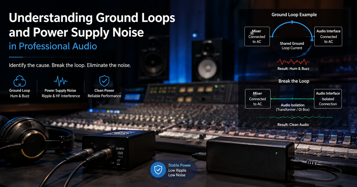
Ground loops and power-supply-coupled noise are among the most persistent challenges in professional audio system design. A well-designed audio circuit can be rendered unusable by a ground loop that introduces 50Hz or 60Hz hum, or by power supply ripple that elevates the noise floor. These issues often appear not in the individual device but when multiple devices are interconnected in a system—making them difficult to predict from component-level specifications alone.
This guide covers the mechanisms of ground loop formation and power supply noise coupling in professional audio equipment, with practical design strategies for OEMs to minimize these effects at the product level. The focus is on how the external power adapter, cable, and grounding architecture interact with the audio signal path.
What Causes a Ground Loop?
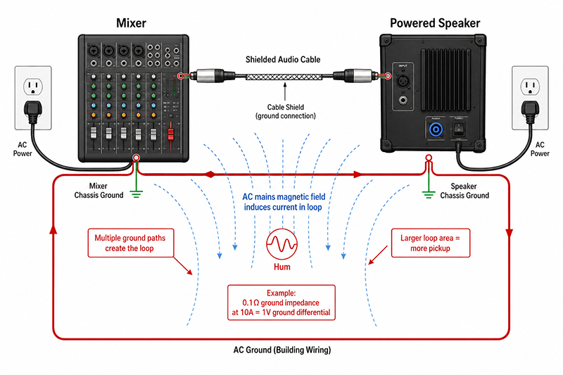
A ground loop occurs when there are multiple paths to ground between interconnected audio devices, creating a closed loop that picks up electromagnetic interference. The classic scenario: two audio devices (e.g., a mixer and a powered speaker) connected by a shielded audio cable, each powered from a different AC outlet. The shield of the audio cable connects the chassis grounds of both devices, while the AC power ground (protective earth) connects them through the building wiring. The result is a loop that acts as a single-turn transformer secondary, coupling magnetic fields from the AC mains wiring and other equipment into the audio signal path.

Key factors in ground loop formation
| Factor | Contribution | Design Implications |
|---|---|---|
| Multiple ground paths | Creates the loop | Minimize ground connections between interconnected devices |
| AC mains magnetic field | Induces current in the loop | Loop area determines coupling; larger loops = more pickup |
| Ground impedance differences | Causes voltage between grounds | 0.1Ω at 10A = 1V ground differential between devices |
| Shield current | Audio cable shield carries loop current | Shield current creates voltage drop across shield resistance, coupling into signal |
Identifying ground loop symptoms
- 50Hz or 60Hz hum (fundamental mains frequency)
- 100Hz or 120Hz buzz (rectified mains)
- Hum varies when devices are moved or reconnected
- Hum present when equipment is grounded but not when lifted
- Hum changes with load on the AC circuit (e.g., when other equipment turns on)
Why This Matters
- Ground loops are a system-level problem, not a single-device problem. An audio product that tests clean in the lab may develop hum when installed in a real system with other interconnected equipment.
- The external power adapter’s grounding configuration (Class I with protective earth vs Class II with double insulation) directly affects whether the equipment introduces or breaks ground loops.
- A ground loop hum of 60Hz at −60dBu may be unnoticeable in a live sound system but unacceptable in a recording studio environment.
What OEMs Should Do Now
- During product design, evaluate the equipment’s grounding architecture for potential ground loop paths when interconnected with other devices through audio cables.
- Consider whether Class II (double-insulated, 2-prong) or Class I (grounded, 3-prong) power architecture is appropriate for your equipment’s typical installation environment.
- Include a ground lift switch or signal isolation (transformers, differential drivers) in equipment designed for interconnection with multiple other devices.
How Power Supply Noise Couples Into the Audio Signal Path
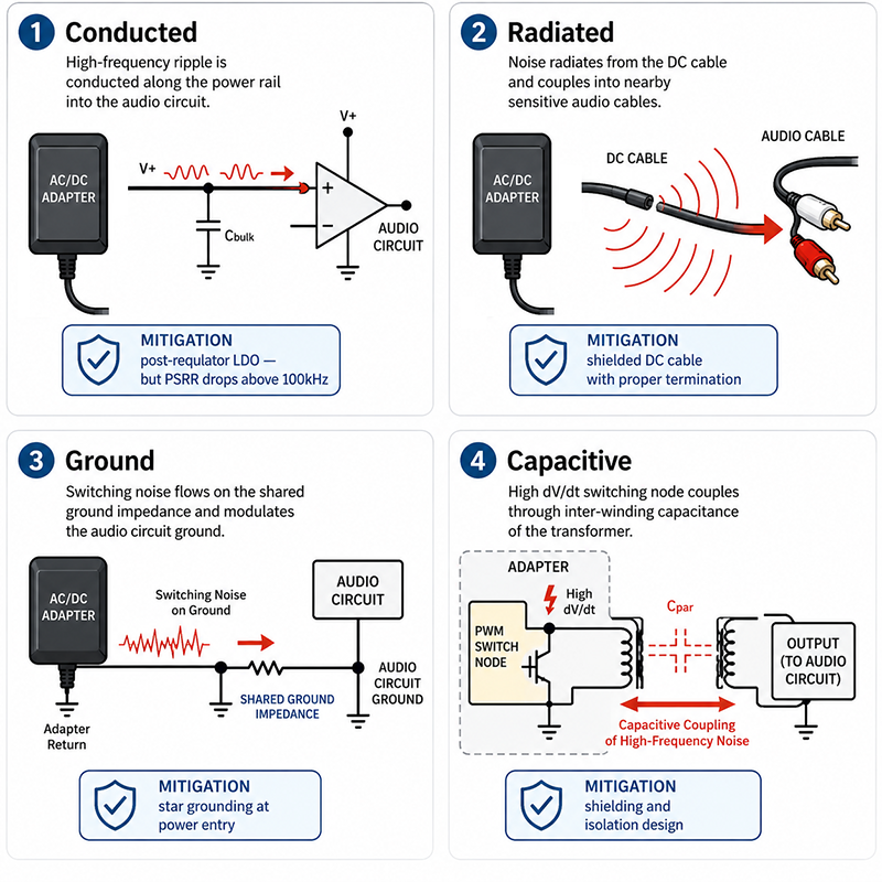
Power supply noise can enter the audio signal path through several mechanisms. Understanding these coupling paths is essential for designing effective mitigation.
Conducted coupling — Ripple and noise on the DC power rail couple directly into the audio circuit through the power supply pins of op-amps and converters. The circuit’s PSRR attenuates this noise, but PSRR is frequency-dependent and typically decreases at higher frequencies. An op-amp with 80dB PSRR at 100Hz may have only 20dB PSRR at 100kHz, making high-frequency switching noise from the adapter a greater concern than low-frequency ripple.
Radiated coupling — The DC cable between the adapter and the audio equipment can act as an unintentional antenna, radiating switching noise that couples into nearby audio circuitry, cable shields, or PCB traces. This is particularly relevant when the DC cable runs parallel to audio cables or is routed near sensitive input stages.
Ground coupling — Switching noise from the adapter’s internal converter can couple into the ground reference of the audio equipment through the ground path shared by the adapter DC return and the audio circuit ground. This is influenced by the adapter’s ground architecture (single-point vs distributed) and the PCB layout of the audio equipment.
Capacitive coupling — The switching node of the adapter’s converter has high dV/dt (voltage slew rate), which can capacitively couple through the transformer, through the adapter enclosure, or across isolation barriers into the DC output and ground.
Why This Matters
- A post-regulator (LDO) between the adapter output and the analog audio rail can attenuate low-frequency ripple by 60–80dB but may provide little attenuation above 100kHz—the frequency range where switching noise can be most problematic.
- The DC cable itself can be a dominant noise coupling path. A 1m unshielded DC cable can radiate more switching noise than the adapter’s internal filtering is designed to suppress.
- Reducing adapter switching noise at the source (adapter design) is more effective than attempting to filter it at the audio equipment input, but the adapter selection determines what noise the audio equipment must handle.
What OEMs Should Do Now
- Map the noise coupling paths in your equipment: conducted (power rail), radiated (cable and enclosure), ground (shared return), and capacitive (high-dV/dt coupling). Address each path with appropriate mitigation.
- For conducted noise, evaluate the PSRR of your voltage regulator and signal-path ICs at the adapter’s switching frequency. If PSRR is insufficient at that frequency, consider a multi-stage regulation approach.
- For radiated noise from the DC cable, evaluate shielded DC cables with appropriate termination for your system’s grounding architecture. Shield termination should be defined based on system-level EMC testing.
Grounding Architecture Decisions for Audio OEMs

The grounding architecture of an audio product determines its susceptibility to ground loops and its interaction with interconnected equipment. Three primary architectures are used in professional audio equipment:
Class I (Grounded / Protective Earth) — The equipment chassis is connected to protective earth through the power adapter’s ground pin (3-prong IEC inlet). The audio signal ground may be referenced to chassis ground through a low-impedance connection or a ground-lift network. This architecture provides safety grounding and can reduce radiated emissions, but creates additional ground loop paths when multiple Class I devices are interconnected.
Class II (Double-Insulated / Ungrounded) — The equipment uses double insulation and does not require a protective earth connection. The adapter is a 2-prong type without a ground pin. Audio signal ground is referenced to the adapter’s DC return, which is isolated from AC mains. This architecture breaks the ground loop path through AC power, but the equipment chassis may float relative to protective earth, potentially increasing noise pickup from nearby electric fields.
Balanced (Differential) I/O — Audio inputs and outputs use differential signaling (XLR or TRS with balanced drivers and receivers). The signal is transmitted as the difference between two conductors, so common-mode noise picked up on the cable is rejected by the receiver’s common-mode rejection ratio (CMRR). Balanced I/O does not eliminate ground loops but reduces their effect on the signal.
The key distinction: balanced audio signaling and protective earth are different design concepts. The need for a protective-earth connection depends on the equipment’s safety class, chassis construction, grounding architecture, EMC design, and applicable certification requirements—not on whether the product uses balanced XLR or TRS interfaces.
Why This Matters
- Class II (ungrounded) equipment eliminates one ground loop path but may have higher chassis potential relative to earth, causing noise coupling through cable shields.
- Class I equipment with a properly designed ground-lift switch can operate in both grounded and lifted configurations, addressing ground loop issues in the field without requiring hardware modification.
- Balanced I/O provides common-mode rejection of 60–90dB at low frequencies, but CMRR degrades at high frequencies due to cable capacitance imbalance and receiver input capacitance mismatch.
What OEMs Should Do Now
- Evaluate whether your equipment’s typical installation environment uses grounded outlets. In many regions, older buildings may have ungrounded or poorly grounded outlets, which affects Class I equipment behavior.
- If designing Class I equipment for interconnection with other devices, consider adding a ground-lift switch or removable ground pin that allows the installer to break the ground loop when necessary.
- For balanced audio outputs, specify CMRR requirements for the balanced line driver and ensure PCB layout preserves symmetry to maintain high-frequency CMRR.
Practical Mitigation Strategies

The following design strategies can reduce ground loop and power supply noise coupling in audio equipment:
| Strategy | Mechanism | Implementation | Trade-off |
|---|---|---|---|
| Ground lift switch | Breaks the AC ground connection | Switch between chassis ground and protective earth | Safety risk if misused; must meet certification requirements |
| Signal isolation transformer | Galvanically isolates signal ground | Transformer on input/output audio lines | Cost, size, low-frequency response roll-off, distortion |
| Differential (balanced) I/O | Common-mode noise rejection | Balanced line drivers and receivers | Higher component cost, increased PCB area |
| Post-regulator LDO | Attenuates power rail noise | LDO between adapter input and analog rail | Voltage drop, power dissipation, limited HF attenuation |
| Shielded DC cable | Reduces radiated coupling | Braided or foil shield on adapter cable | Shield termination must match grounding architecture |
| Ferrite common-mode choke | Suppresses common-mode noise | Ferrite on DC cable near equipment entry point | Adds cost; requires testing for optimal placement |
| Separate analog/digital ground planes | Reduces digital noise coupling into analog | Star grounding at power entry point | PCB layout complexity |
| Ground loop isolation in cable | Breaks shield loop | Ground-lift adapter on audio cable (pin 1 lift) | Signal integrity depends on cable design |
Why This Matters
- No single mitigation strategy solves all ground loop problems. Multiple strategies are typically used in combination.
- The most effective approach is to prevent ground loops at the system architecture level, rather than attempting to fix them with add-on components after the design is complete.
- Mitigation strategies that work in the lab may not work in all field installations. Consider the range of installation environments your equipment will encounter.
What OEMs Should Do Now
- During the design phase, identify potential ground loop paths and evaluate which mitigation strategies are appropriate for your equipment’s form factor, cost target, and target market.
- Include a ground lift option (switch or removable ground pin) in equipment designed for professional installation where ground loops are likely.
- Test the final design with representative interconnected equipment (mixer, amplifier, powered speaker) to verify ground loop and noise performance in a system context.
Q: Does a shielded audio cable prevent ground loops?
A: A shielded cable connects the chassis grounds of two devices through the shield conductor, which can create a ground loop. The shield is necessary for EMI protection, but the loop formed by the shield and the AC mains ground path is what causes the hum. Breaking the loop (via ground lift or isolation) while maintaining shielding is the design challenge.
Q: Can I use a 3-prong to 2-prong adapter (ground lift cheater) to fix a ground loop?
A: Ground lift cheater plugs remove the protective earth connection, which creates a safety hazard—the equipment chassis may become live if a fault occurs. Professional audio equipment with a ground lift switch is designed for this purpose with appropriate safety certifications. A cheater plug should not be used as a permanent solution.
Q: How does the external power adapter affect ground loops?
A: The adapter’s isolation architecture determines the relationship between the DC output ground and AC mains. A Class II adapter (2-prong, double-insulated) provides galvanic isolation without a protective earth connection, which can reduce ground loop paths. A Class I adapter (3-prong, grounded) provides protective earth but adds a ground loop path through the AC mains. The choice depends on the equipment’s safety class, grounding architecture, and installation environment.
CONCLUSION
Ground loops and power-supply-coupled noise are system-level challenges that require careful attention to grounding architecture, power adapter selection, and audio signal path design. The key principles are: understanding the difference between protective earth, signal ground, and cable shield; selecting the appropriate grounding architecture (Class I vs Class II) for the equipment’s installation environment; designing balanced I/O with adequate CMRR; and using a combination of mitigation strategies appropriate to the application.
Related Resources
🔌 Related Products
🏭 Related Applications
📖 Related Guides
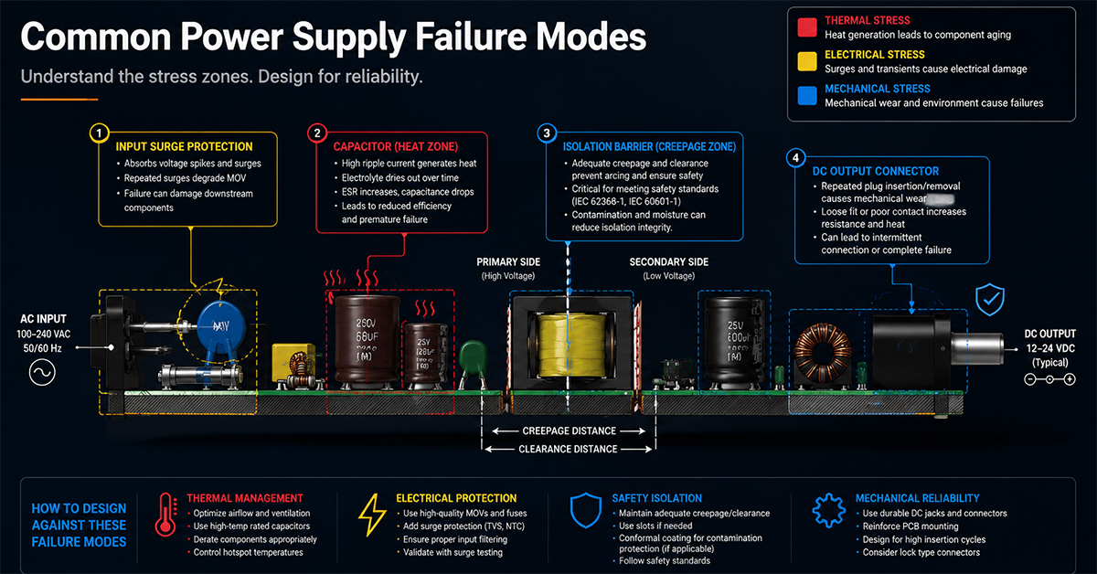
Common Power Supply Failure Modes
Common power supply failure modes and design countermeasures
✅ Related Certifications
UL 62368-1 Safety Certification
Safety standard covering connector creepage/clearance, temperature rise, and strain relief requirements for IT/AV equipment power adapters.