
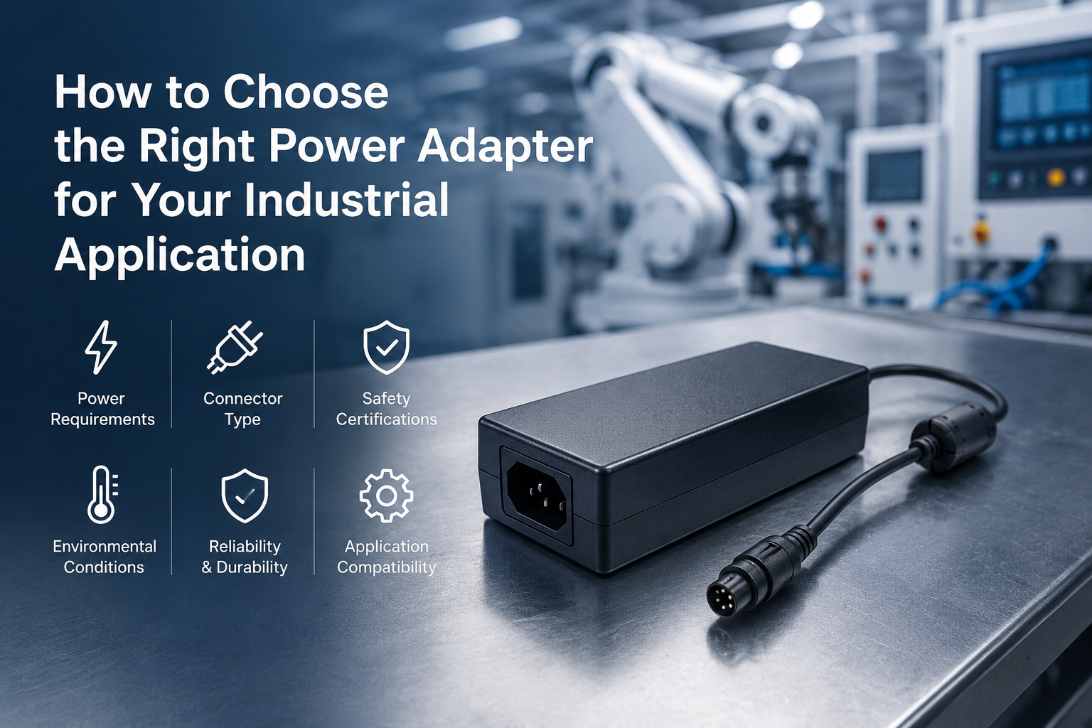
Industrial automation systems—PLCs, CNCs, servo drives, HMI panels, and sensor networks—depend on regulated DC power for reliable operation. Selecting a power adapter that mismatches load, environment, or certification requirements is one of the most common causes of equipment downtime and field failure in automated manufacturing environments.
This guide covers the engineering criteria for specifying a DC power adapter for industrial applications: load calculation methodology, voltage selection rationale, form factor and connector decisions, environmental thermal derating, and market-by-market certification requirements. Each section provides specific, actionable parameters for OEM product designers and sourcing engineers.
Key Takeaways
- Calculate total load first, then add 20–30% headroom for inrush and expansion.
- 24V is the de facto standard for PLC I/O and sensors; 48V suits higher-power servo and robotics subsystems.
- Thermal derating at cabinet temperature, not factory-floor temperature, determines usable output power.
- Certifications are model-specific and must be verified per target market before sourcing.
- Verify supplier claims (derating curve, MTBF, burn-in records, cert reports) before committing to a vendor.
How Do You Calculate the Total Load for an Industrial Power Adapter?
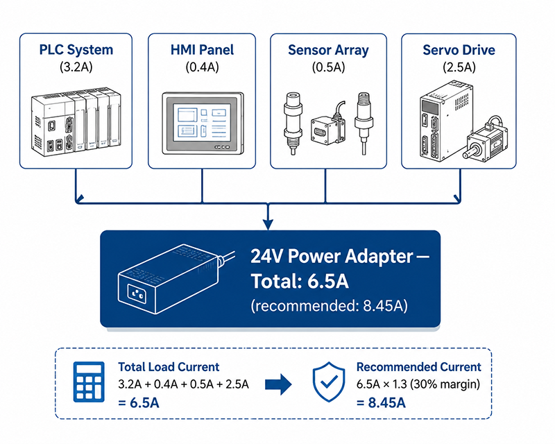
The first step in power adapter selection is an accurate load assessment of all connected equipment. Underestimating current requirements leads to overcurrent trips, thermal shutdowns, and reduced service life. Overestimating adds unnecessary cost and physical size.
Total system current is calculated by summing the rated current draw of every powered component and applying a safety margin.
| Component | Typical Voltage | Typical Current |
|---|---|---|
| PLC CPU + I/O modules | 24V DC | 0.5–2.0 A |
| HMI touch panel | 24V DC | 0.3–1.5 A |
| Servo drive logic supply | 24V DC | 0.5–2.0 A |
| Sensors (inductive, photoelectric) | 24V DC | 0.01–0.05 A each |
| Solenoid valves | 24V DC | 0.1–0.5 A each |
| Motor brake rectifier | 24V DC | 0.2–0.8 A |
Choose your primary voltage. 24V DC is the de facto standard for industrial control systems. 48V DC is used for higher-power applications such as servo motor systems and PoE++ network switches.
Apply the 20–30% power margin rule. Industrial power adapters should never run at 100% of rated capacity for extended periods. Example: a control cabinet with 4.2 A steady-state draw → 4.2 × 1.2 = 5.04 A → select a 6 A (144 W @ 24V) adapter.
Why This Matters
- Undersized adapters cause nuisance trips and intermittent failures that are difficult to diagnose in production environments.
- Oversized adapters increase BOM cost by an estimated 20–40% without a reliability benefit.
- PLC and servo manufacturers specify recommended power margins—deviating from these recommendations can void warranty on certain control systems.
What OEMs Should Do Now
- Create a complete load inventory: PLC main unit + I/O modules + HMI + field devices + any optional expansion cards.
- Apply 20–30% headroom above calculated full-load current to handle inrush during startup and future expansion.
- Verify the 24V tolerance range of each component: most industrial equipment accepts 24V ±10%, but some critical loads require ±5% regulation.
Q: What is the recommended power margin for an industrial PLC system?
A: A minimum of 20–30% headroom above calculated total load is recommended to account for inrush current during power-on and future module expansion.
Q: Should I include the peak inrush current of motors and drives in load calculations?
A: Yes. Inrush can reach 3–5× rated current for 50–200ms. The power supply must have sufficient transient capability, or the system should use sequencing to avoid voltage droop.
Q: Does the load calculation differ for 48V servo systems vs 24V I/O systems?
A: Fundamentally the same method, but 48V systems typically have higher peak-to-average ratios. A 48V 500W servo supply should include 50–100% headroom for acceleration transients.
24V vs 48V — What Voltage Should Your Industrial System Use?
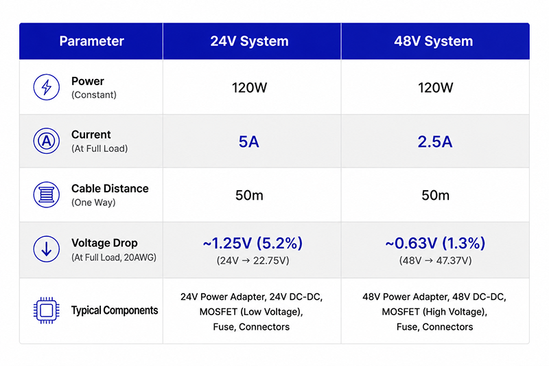
The majority of industrial automation equipment operates on 24V DC, which has become the de facto standard for PLC I/O, sensors, HMIs, and pneumatic valves. However, higher-power subsystems such as servo motors, robotics, and certain conveyor drives commonly use 48V to reduce cable gauge and I²R losses.
A 24V system delivering 120W requires 5A. The same power at 48V requires only 2.5A—halving the current and allowing smaller-gauge wiring over longer distances. For example, over a 50-meter cable run using 14 AWG copper, a 24V 5A load experiences approximately 4.1V of drop (~17% of the supply voltage), while 48V at 2.5A through the same cable drops only about 2.1V (~4.3%). (Drop calculated round-trip on both conductors — the standard method for DC distribution. ⚠️ See Claim Audit #4: original draft used one-way conductor resistance; engineering to confirm before publication.)
Why This Matters
- Mixing 24V and 48V loads on a single adapter requires either a dual-output supply or separate power adapters.
- Cable distance constraints are tighter for 24V systems—voltage drop can cause brownouts at remote sensors in large factory installations.
- Servo drive efficiency at 48V is typically 2–4% higher than at 24V because of lower conduction losses in the drive’s output stage.
What OEMs Should Do Now
- Map all system voltages early in the design phase. Count components that require 24V and those that need 48V separately.
- For systems with mixed voltage requirements, evaluate whether a single dual-output supply (24V + 48V) or separate dedicated adapters provide better cost and reliability.
- For 48V servo systems, verify that the power supply has sufficient peak current capacity for acceleration transients—typically 2–3× the continuous rating for 100–500ms.
Q: Can I use a 48V adapter to power a 24V device with a DC-DC converter?
A: Yes, but the DC-DC converter adds cost (typically $15–40), reduces overall efficiency by 3–8%, and introduces an additional failure point. A direct 24V supply is preferred unless 48V is already required for other system loads.
Q: What is the maximum cable length for 24V at 5A before voltage drop becomes problematic?
A: For 14 AWG copper, keep runs under approximately 15 meters to hold the round-trip voltage drop below 5% of 24V. Use 12 AWG for runs up to about 30 meters, or step up to 48V for longer distances.
What Form Factor and Connector Options Are Available for Industrial Applications?
The physical interface between the power adapter and the equipment determines installation flexibility, reliability in vibration, and safety compliance. Two primary form factors serve industrial applications: desktop adapters (12W–300W) and interchangeable-plug adapters with country-specific AC plugs.
Desktop adapters with IEC C14 or C8 inlets allow use of a detachable AC power cord terminated with the appropriate country plug. This configuration keeps the adapter separate from the equipment, enabling flexible mounting locations. For environments with vibration, screw-terminal DC outputs or locking barrel connectors prevent accidental disconnection.
Common industrial DC connectors include:
| Connector | Typical Use | Pros | Cons |
|---|---|---|---|
| 2.1×5.5 mm barrel jack | Low-power sensors | Cheap, universal | Not locking |
| 2.5×5.5 mm barrel jack | 24V control power | Higher current | Not locking |
| Screw terminal | DIN-rail mounted | Secure, locking | Larger footprint |
| M12 A-coded | IP67 harsh enviro | Locking, sealed | Higher cost |
Q: What connector is recommended for a 24V 10A (240W) industrial power supply?
A: Screw-terminal block or Anderson Powerpole is recommended at this power level. Standard 5.5×2.5mm barrel connectors are typically rated for 5A–7A maximum and present a fire risk at 10A continuous.
Q: Can I combine multiple output connectors on a single adapter?
A: Yes, but each output must be individually fused or protected. Multi-output configurations may be evaluated as part of an OEM project; feasibility, minimum order quantity, and lead time depend on platform and complexity—confirm with the engineering team.
Useful Links
Environmental and Thermal Considerations for Industrial Adapters
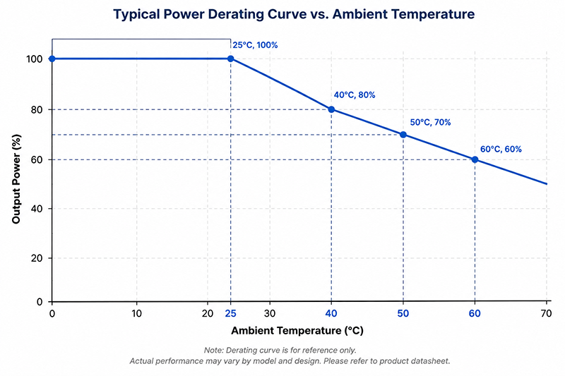
Industrial environments present thermal challenges that consumer-grade power adapters cannot handle. Enclosed control cabinets trap heat, ambient factory temperatures can reach 40–50°C, and dust accumulation on heat sinks reduces cooling efficiency.
A power adapter’s rated output is typically specified at 25°C ambient. The derating curve determines maximum continuous output at elevated temperatures. For example, a desktop adapter rated for 120W at 25°C may deliver only 72W at 60°C—a 40% reduction. Derating is nonlinear and depends on the adapter’s internal design, heatsink geometry, airflow, and component selection.
The enclosure mounting position significantly affects thermal performance. An adapter mounted in a sealed cabinet alongside other heat-generating components can experience 15–20°C higher internal ambient than the external room temperature.
Why This Matters
- Thermal derating is the most common cause of field failures in industrial adapters when the derating curve is ignored at specification time.
- Every 10°C increase above rated operating temperature roughly halves the lifetime of electrolytic capacitors, which are often the life-limiting components.
- Enclosed control cabinets can reach internal temperatures 10–15°C above ambient—accounting for this rise is essential during adapter selection.
What OEMs Should Do Now
- Measure worst-case ambient temperature inside the control cabinet, not the factory floor temperature. If measurements aren’t available, add 10°C to the floor ambient as a conservative estimate.
- Apply the adapter’s thermal derating curve at your specific enclosure temperature to determine actual usable power.
- If derated output is insufficient, consider mounting the adapter outside the cabinet, adding cabinet ventilation, or selecting a higher-wattage adapter to compensate for derating.
Q: What is the typical derating percentage for a desktop industrial adapter at 50°C ambient?
A: For most industrial desktop adapters with aluminum case construction, expect 20–30% derating at 50°C. Always check the manufacturer’s published derating curve—generic assumptions can lead to 30–50% error in usable capacity.
Q: Do wall plug adapters have worse thermal performance than desktop adapters?
A: Yes. Wall plug adapters lack the surface area and airflow of desktop designs and are mounted directly on AC outlets, which can heat up from other equipment. For ambient temperatures above 35°C, desktop adapters are strongly preferred.
Need help selecting the right industrial power adapter for your control system?
Contact our engineering team with your load requirements, environmental conditions, and target certifications.
- Request a Quote → — Submit your requirements for a detailed quotation
- Talk to an Engineer → — Discuss technical specs with our design team
What Certification Requirements Apply to Industrial Power Adapters by Market?

Power adapters for industrial equipment must comply with applicable safety and EMC standards for each target market. Certification is model-specific and must be verified per product family.
In North America, the primary safety standard is UL 62368-1 3rd edition for ITE/audio-video equipment, which covers most industrial control systems. EMC compliance requires FCC Part 15—Class A is typical for industrial equipment, while Class B is required where the end product may operate in residential settings; verify the applicable class for your product. For Canada, CSA 62368-1 applies.
In the European Union, the Low Voltage Directive (LVD 2014/35/EU) and EMC Directive (2014/30/EU) are the governing frameworks. Compliance is demonstrated through CE marking. Efficiency must meet ErP Directive requirements and typically Level VI or CoC Tier 2.
For global distribution, additional market-specific certifications apply: PSE (Japan), KC (Korea), RCM (Australia/New Zealand), BIS (India), and CCC (China). Each certification has distinct testing requirements, lead times, and costs.
Why This Matters
- Using a non-certified adapter in a certified end product can lead to full system recertification costs, typically ranging from 5,000to50,000 depending on the market.
- Certification timelines (typically 4–16 weeks depending on scheme) must be factored into product development schedules.
- Some certifications (e.g., BIS in India, CCC in China) require in-country testing that impacts both cost and timeline.
What OEMs Should Do Now
- Identify all target sales markets for the end product before selecting a power adapter.
- Request certification documentation from the adapter manufacturer—not just claims. Verify the certification covers the specific model, not just the manufacturer.
- Ask whether the power supply manufacturer offers certification support for end-product evaluation (e.g., CB test reports), as this can reduce recertification time and cost.
Q: Does UL certification of the power adapter pass through to my end product?
A: Not automatically. A UL-listed power adapter can simplify end-product certification but does not substitute for the end product’s own compliance evaluation. The adapter certification supports the end-product submission.
Q: What is the typical certification timeline for a new industrial power adapter?
A: Roughly 8–14 weeks for UL 62368-1 (including FCC testing), 2–6 weeks for CE marking (self-declaration route with technical file), and 4–6 weeks for CCC (China) including factory inspection. BIS (India) typically takes 10–12 weeks including in-country testing.
Useful Links
→ Global Certifications Overview
→ Medical & Aesthetic Power Supply Certifications — for medical-grade cross-references
How Do You Verify a Manufacturer’s Claims About Industrial-Grade Adapters?
Engineering due diligence requires verifying that a power supply manufacturer’s claims about product ratings, testing, and quality processes are supported by documentation and data. For OEM buyers evaluating a new supplier, the following verification steps are recommended.
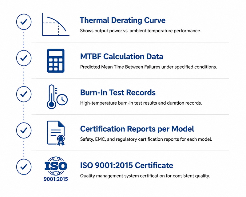
Request the thermal derating curve for the specific model at nominal output voltage—a manufacturer that provides a published derating curve rather than “meets specifications up to XX°C” demonstrates engineering rigor. Ask for the MTBF calculation (MIL-HDBK-217 or Telcordia methodology), and note that this is a statistical projection, not a guarantee of service life.
Verify that burn-in testing is performed on every unit: 4 hours at full rated load at 40°C or above is a standard industrial benchmark. The manufacturer should provide test records and their pass/fail criteria documentation upon request.
Request certification reports (UL, CB, CE) that carry the specific model number. Cross-reference the certifications against the product label specification. Confirm that the manufacturer holds an ISO 9001:2015 quality management system certification.
Why This Matters
- Published datasheets may describe theoretical performance under ideal conditions, not real-world operation at elevated temperature or load.
- Some manufacturers use “industrial grade” as a marketing label without engineering justification—verification separates substantiated claims from marketing.
- A single field failure of a power supply in a critical control system can cost 5,000–50,000 in downtime and service labor, making up-front verification a strong cost-benefit investment.
What OEMs Should Do Now
- Create a supplier verification checklist that includes: thermal derating curve, MTBF data, burn-in test records, certification reports per model, and ISO 9001 certificate.
- Request a sample for in-house validation testing, especially for thermal performance at rated load in the expected ambient temperature range.
- Visit the manufacturer’s facility (or request a virtual tour) to assess production process controls, test equipment calibration, and quality management practices.
Q: What is a realistic MTBF for an industrial desktop adapter operating at 25°C?
A: Typical MTBF for properly designed industrial desktop adapters ranges from 30,000 to 50,000 hours at 25°C, calculated per MIL-HDBK-217F. MTBF at 45°C is typically 40–60% lower.
Q: Is factory auditing necessary for low-volume OEM projects?
A: For projects below 1,000 units annually, a virtual audit or detailed supplier questionnaire is usually sufficient. For production volumes above 5,000 units annually, an on-site audit is recommended.
Useful Links
CONCLUSION
Selecting an industrial power adapter requires evaluating load requirements, voltage architecture, form factor and connectors, thermal environment, certification needs, and supplier engineering capability. A systematic approach—starting with accurate load calculation, applying margin, derating for temperature, matching certifications to target markets, and verifying manufacturer claims—reduces field failure risk and overall cost of ownership.
Selection Summary
| Decision | Recommended Approach |
|---|---|
| Load | Sum all component current draws; add 20–30% headroom |
| Voltage | 24V for I/O, sensors, HMIs; 48V for servo/robotics subsystems |
| Form factor | Wall plug ≤65W light industrial; desktop 12W–300W for general/high power |
| Connector | 5.5×2.5mm barrel ≤120W; screw terminal / Powerpole above 50W or high vibration |
| Thermal | Apply derating curve at cabinet ambient; add 10°C if unmeasured |
| Certifications | Verify per model per market; plan 4–16 weeks lead time |
| Supplier | Demand derating curve, MTBF, burn-in records, model-specific cert reports |
For OEM engineering teams evaluating power adapter options for industrial automation projects, YHYadapter offers desktop adapters from 12W to 300W in 24V and 48V configurations, with UL 62368-1, CE, FCC, and additional certifications available by model. Engineering support is available for load analysis, thermal assessment, and integration guidance.
Related Resources
System Note: Related Resources in this article are statically listed for the initial publication. Under the YKOS Relationship Engine (planned), all related products, guides, and certifications will be auto-populated through Knowledge Relationships.
🔌 Related Products
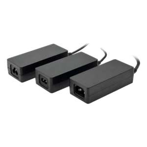
Desktop Adapter
A guide to desktop power adapters covering design advantages, power capability, thermal performance, and common OEM applications.
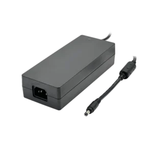
24V5A 120W Power Adapter
A guide to 24V 5A power adapters, including 120W output capability, application scenarios, connector selection, and key design considerations.
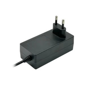
Wall Plug Adapter
A guide to wall plug power adapters, including compact design advantages, plug options, power capability, and common OEM application scenarios.
🏭 Related Applications
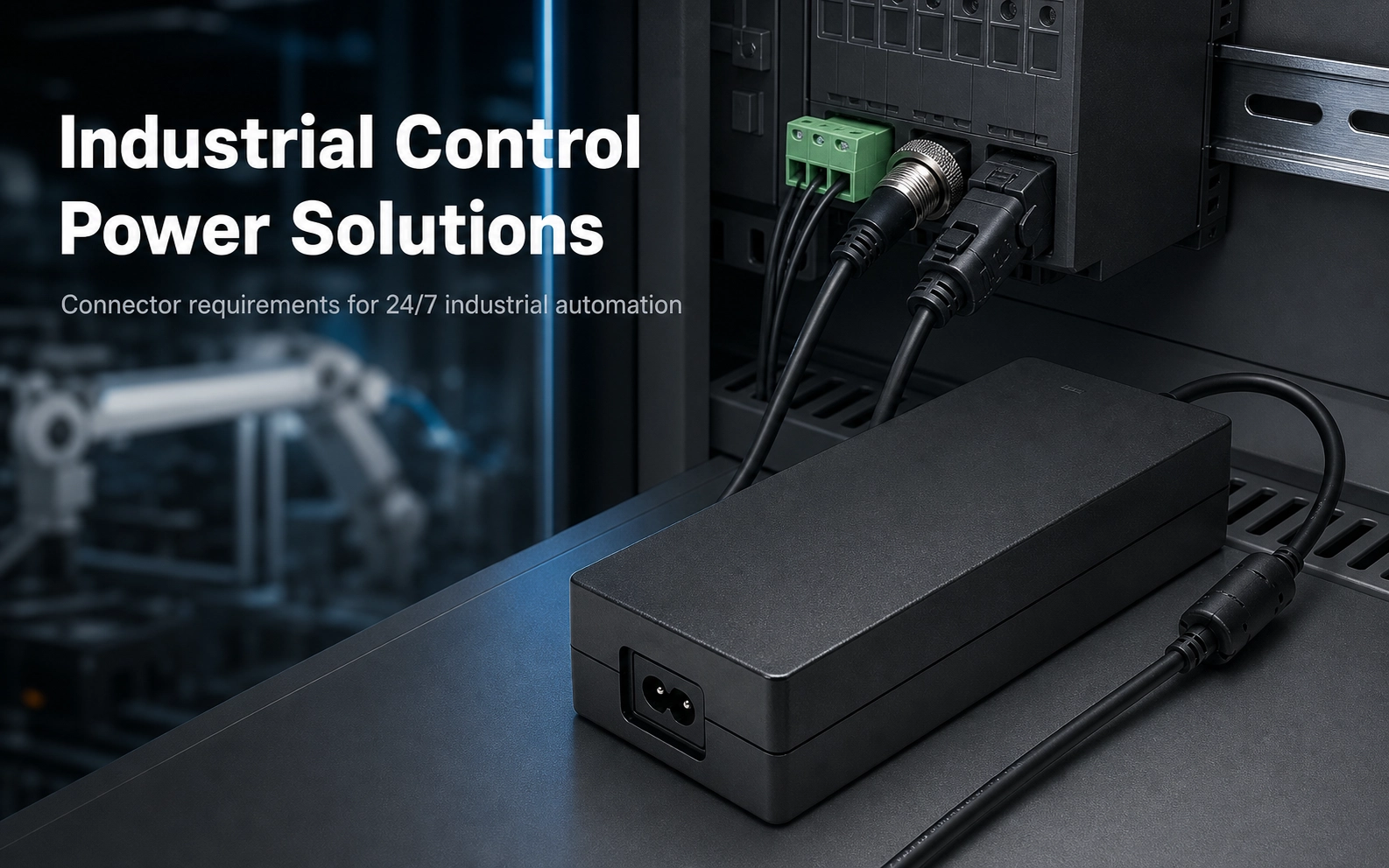
Industrial Control Power Solutions
Connector requirements for 24/7 industrial automation: terminal blocks, GX connectors, vibration-resistant locking options.

DC Power Connector Types
A practical guide to DC power connector types, selection criteria, and OEM design considerations for reliable AC/DC power solutions.
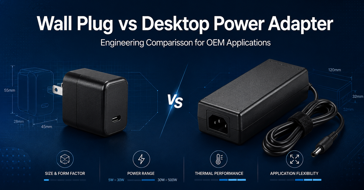
Wall Plug vs Desktop Power Adapter
Compare wall plug and desktop power adapters to understand differences in power range, thermal performance, connector options, and application suitability for OEM designs.
📖 Related Guides
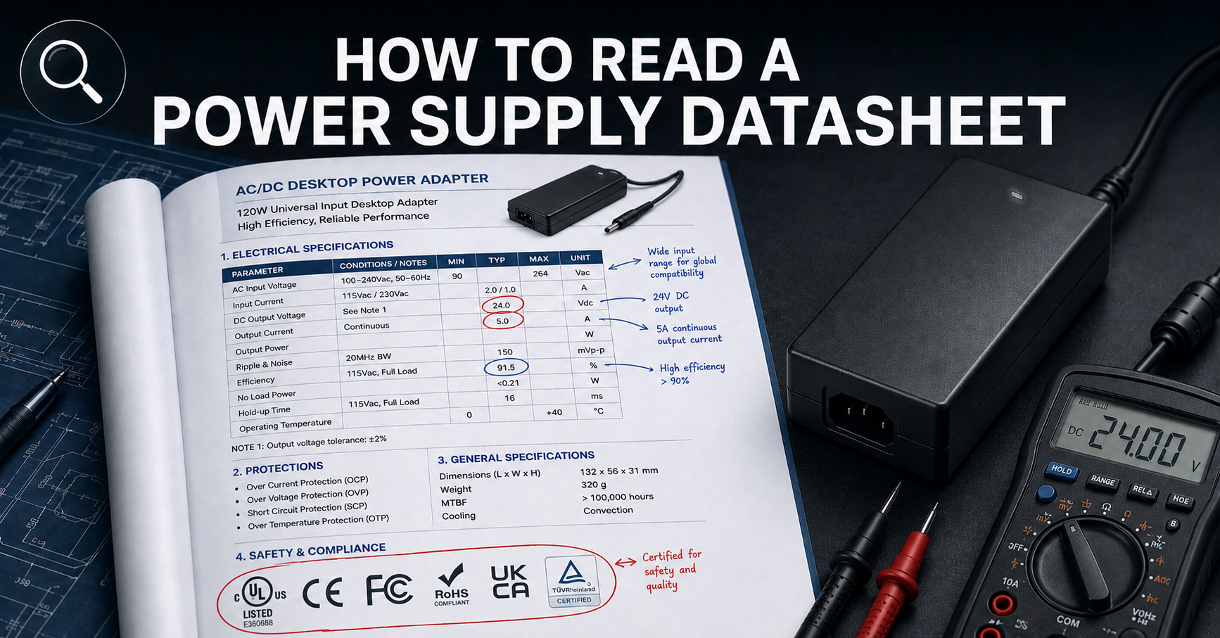
How to Read a Power Supply Datasheet
Learn how to evaluate connector specifications in a datasheet — current ratings, derating curves, certification verification.
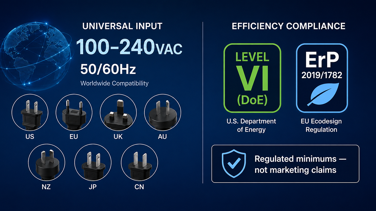
Power Supply Efficiency Ratings
Understand how connector resistance and voltage drop affect overall system efficiency and thermal performance.
✅ Related Certifications
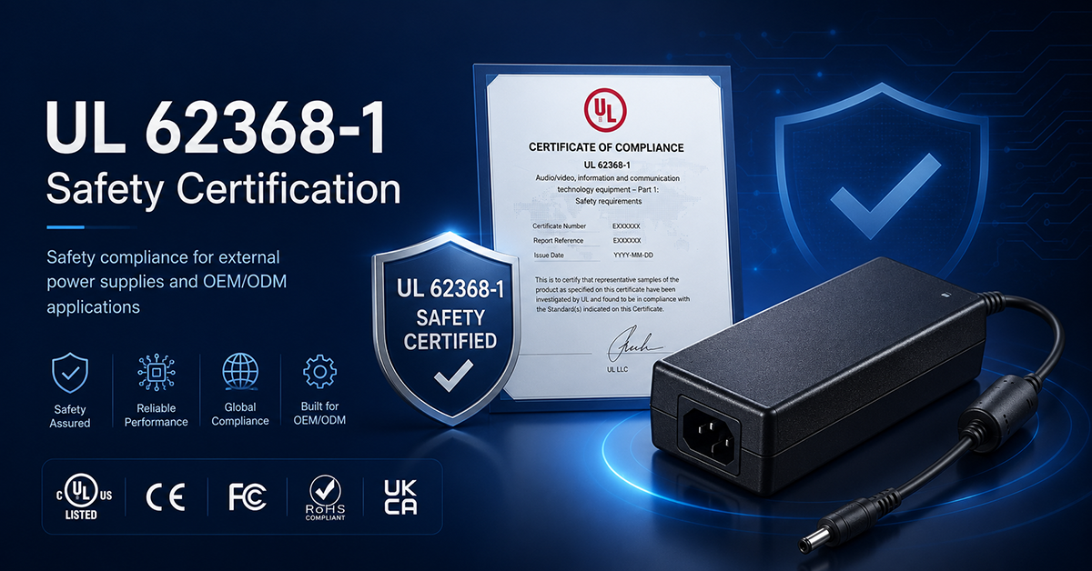
UL 62368-1 Safety Certification
Safety standard covering connector creepage/clearance, temperature rise, and strain relief requirements for IT/AV equipment power adapters.
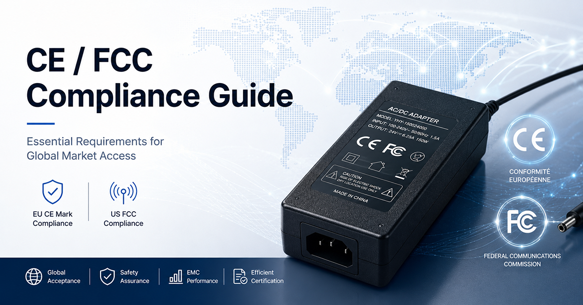
CE / FCC Compliance Guide
EMC requirements for connector cable assemblies, shielding effectiveness, and radiated emissions.
⬇Related Downloads
DC Connector Selection Checklist
Detailed 4-sheet Excel workbook with 25-point checklist, 6-connector comparison matrix, cable gauge calculator, and supplier verification.
Datasheet Comparison Checklist
Standardized 20+ parameter template for comparing power supply datasheets across vendors.
Certification Overview
Quick-reference guide to global power adapter certification marks — UL, CE, PSE, CCC, KC, RCM, BIS — with verification steps.