YHYadapter product positioning: YHYadapter provides regulated constant-voltage (CV) AC/DC power adapters suitable for use within LED lighting systems. Dedicated constant-current LED drivers with integrated dimming interfaces are available from specialized lighting driver manufacturers. The dimming protocol information in this guide serves as industry reference for OEMs designing LED lighting systems.
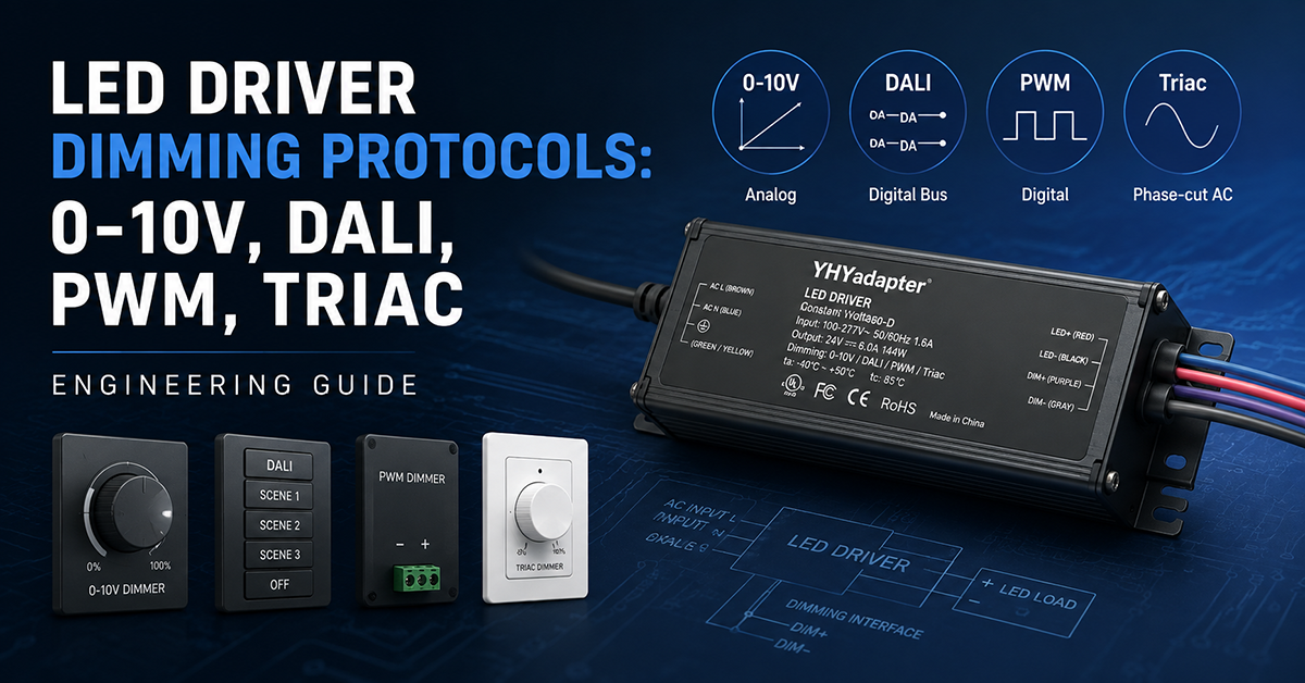
Dimming is a standard requirement for commercial, architectural, and many residential LED lighting installations. The dimming protocol determines how the luminaire communicates with the control system, and the choice of protocol affects driver selection, wiring infrastructure, commissioning, and user experience. Each protocol has distinct electrical characteristics, wiring requirements, and compatibility constraints that OEMs must consider when designing LED luminaires.
This guide covers the four dominant dimming protocols used in LED lighting: 0–10V, DALI, PWM, and Triac (phase-cut). It addresses the electrical interface, wiring requirements, compatibility considerations, and design guidance for each protocol. This is presented as industry knowledge to inform OEM design decisions; specific product capabilities should be verified with individual driver manufacturers.
0–10V Analog Dimming
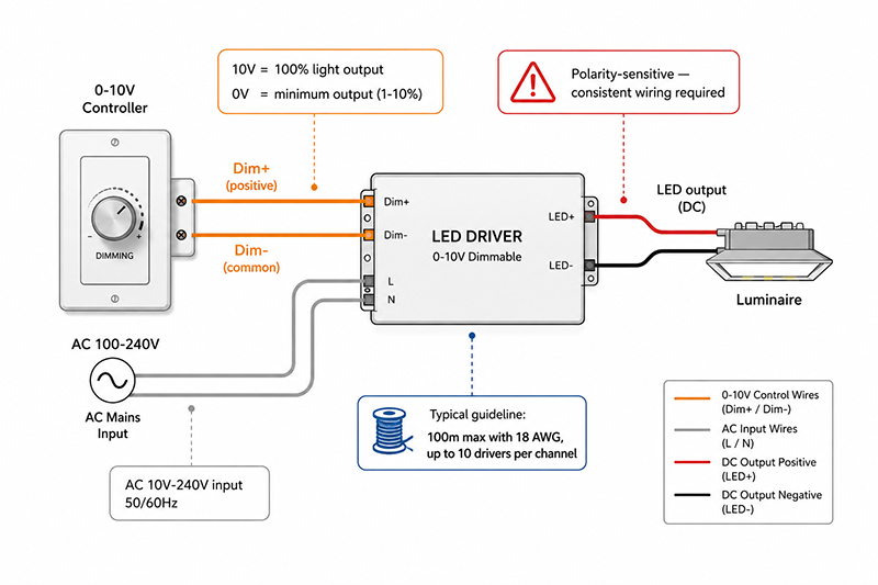
0–10V dimming is the most widely used analog dimming protocol for commercial LED lighting. It is specified in IEC 60929 Annex E for fluorescent lamp control and has been adopted as a standard interface for LED drivers.
Electrical Characteristics
- Signal: Analog DC voltage on two control wires (dimming positive and dimming common)
- Control range: 10V = 100% light output; 0V = minimum output (typically 1–10% depending on driver design)
- Polarity: Polarity-sensitive—reversing the control wires may prevent dimming or cause erratic behavior
- Current sourcing: The control system (or wall station) sources current to the driver’s dimming input. The driver presents a defined input impedance.
- Isolation: 0–10V control circuits are typically SELV (Safety Extra-Low Voltage) and are isolated from the AC mains within the driver.
Wiring
- Two low-voltage wires (18–22 AWG typical) from the control system to each driver or luminaire
- Maximum cable length depends on wire gauge and the number of drivers on a single control channel. A typical guideline: 100m with 18 AWG for up to 10 drivers
- 0–10V wiring can share conduit with AC mains wiring in some jurisdictions. Verify local electrical code requirements.
Compatibility Considerations
| Factor | Consideration |
|---|---|
| Driver compatibility | Most commercial-grade LED drivers support 0–10V dimming. Verify the driver’s control input specification. |
| Multiple drivers per channel | Multiple drivers can be connected to one 0–10V control channel if the total input current does not exceed the controller’s output current capability. |
| Minimum dimming level | The minimum dimming level is specified in the driver’s datasheet. Dimming below the specified minimum may cause the driver to shut off or operate with excessive current ripple. |
| Polarity | Control wires are polarity-sensitive. Consistent wiring across all drivers on a channel is required. |
| Flicker | Well-designed 0–10V drivers produce smooth, flicker-free dimming. Flicker may occur if the driver is not compatible with the control system or if wiring is incorrect. |
Typical Applications
- Commercial office lighting
- Conference rooms and classrooms
- Warehouse and industrial lighting
- Any installation where simple, reliable dimming is required without digital addressing
Why This Matters
- 0–10V dimming is the most compatible and widely supported protocol across LED driver manufacturers, making it a safe choice for multi-vendor projects.
- The polarity sensitivity of 0–10V wiring means that consistent field wiring is essential. Color-coded or labeled wiring is recommended to reduce installation errors.
- The minimum dimming level varies between driver models. OEMs should specify the expected minimum dimming level in their luminaire specifications.
DALI Digital Dimming
Electrical Characteristics
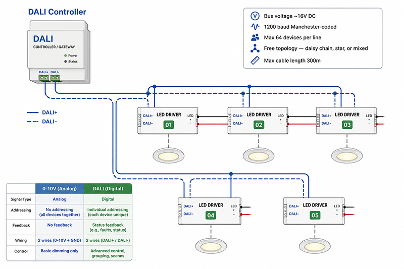
- Signal: Digital data on a two-wire bus (DALI+ and DALI−) using Manchester-coded communication at 1200 baud
- Bus voltage: Approximately 16V DC, supplied by a DALI bus power supply (typically integrated into a DALI controller or gateway)
- Addressing: Each DALI device has a unique address (64 devices maximum per DALI line). Devices can be grouped into up to 16 groups and up to 16 scenes.
- Isolation: The DALI bus is SELV. The driver must provide galvanic isolation between the DALI bus and the AC mains, and between DALI and the LED output.
Wiring
- Two wires (DALI+ and DALI−) in a free-topology bus (daisy chain, star, or any combination)
- Maximum cable length: 300m (limited by communication at 1200 baud)
- Polarity: DALI bus wires are polarity-sensitive on some driver implementations; polarity-independent DALI-2 devices are becoming more common
- DALI wiring can share conduit with AC mains in some jurisdictions. Verify local code.
DALI-2 vs DALI Version 1
Comparison with 0–10V
| Feature | 0–10V | DALI |
|---|---|---|
| Control type | Analog | Digital |
| Wiring | 2-wire, polarity-sensitive | 2-wire bus, polarity-sensitive (DALI-2 may be polarity-independent) |
| Addressability | None (all drivers respond together) | Individual addressing, grouping, scenes |
| Feedback | None | Status feedback (lamp failure, driver error) |
| Commissioning | Simple (wire and test) | Requires commissioning tool for addressing |
| Cost per driver | Lower | Higher |
| Complexity | Low | Moderate |
Why This Matters
- DALI enables per-luminaire addressing and flexible grouping that cannot be achieved with 0–10V analog control.
- DALI commissioning requires specialized software and training, adding to installation cost compared to 0–10V.
- DALI-2 certification improves interoperability. Specifying DALI-2 certified drivers is recommended for multi-vendor projects.
PWM Dimming
Electrical Characteristics
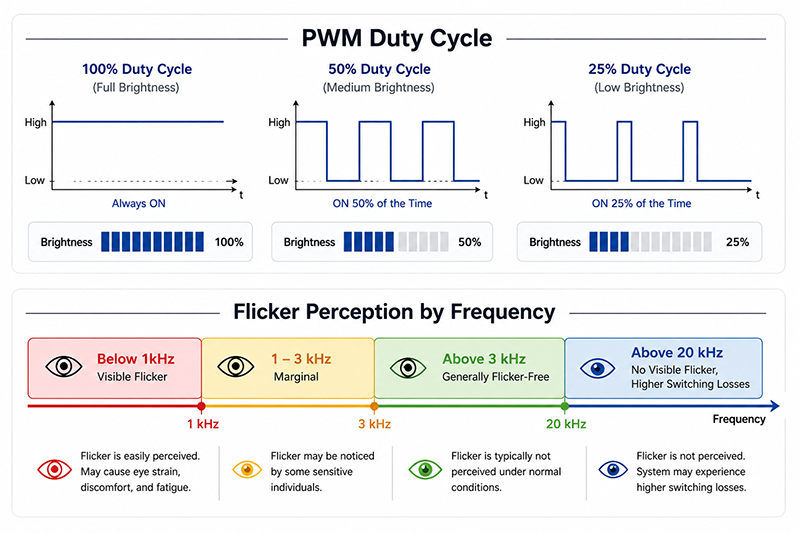
- Signal: Digital PWM input typically 0–5V or 0–10V logic, variable duty cycle
- Frequency: Typically 200Hz–20kHz, depending on driver design and application requirements
- Control range: 0–100% duty cycle, where 100% duty cycle = 100% light output
Flicker Considerations
- Frequencies below 1kHz may be perceptible as flicker, particularly in peripheral vision or during eye movements
- Frequencies above 3kHz are generally considered flicker-free for most people
- Frequencies above 20kHz eliminate visible flicker entirely but increase switching losses in the driver and may cause EMI issues
- Some applications (e.g., camera-recorded environments) require higher PWM frequencies to avoid strobe effects in video
Compatibility
- Requires a driver with a PWM dimming input
- CV systems using external PWM controllers can modulate the LED current; CC drivers may include a PWM dimming input on the control side
- PWM input is less standardized than 0–10V and DALI. Verify the PWM voltage levels and frequency range accepted by the specific driver.
Why This Matters
- PWM dimming at low frequencies can cause visible flicker that affects occupant comfort and may be unacceptable in commercial lighting installations.
- PWM dimming is common in simple controllers and color tuning systems (RGB/CCT) where each channel is independently controlled.
- The PWM input frequency and voltage levels should be verified against the driver’s specification. Compatibility cannot be assumed from PWM presence alone.
Triac (Phase-Cut) Dimming
Electrical Characteristics
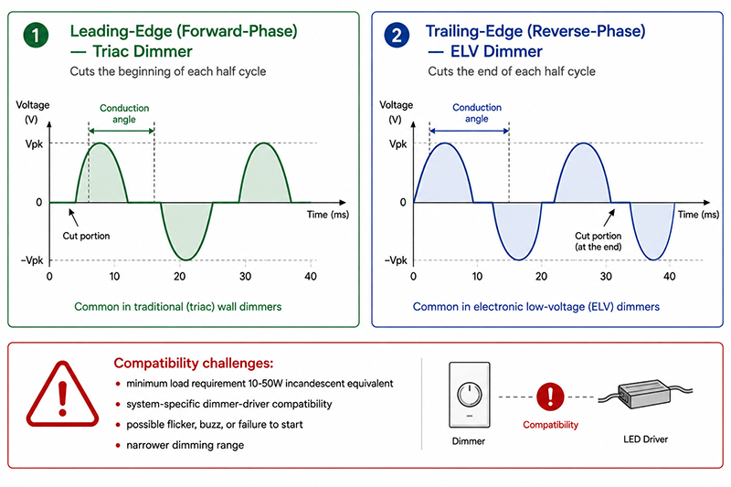
- Signal: AC mains voltage with the leading edge or trailing edge of each half-cycle cut (phase-cut) by the dimmer
- Leading-edge (forward-phase): The Triac dimmer cuts the leading edge of each half-cycle. This is the most common type in residential incandescent dimmers.
- Trailing-edge (reverse-phase): The dimmer cuts the trailing edge. Common in electronic low-voltage (ELV) dimmers and some newer LED-specific dimmers.
Compatibility Challenges
- Minimum load requirement: Triac dimmers require a minimum load current (typically 10–50W incandescent equivalent) to maintain reliable Triac conduction. LED loads may be below this minimum, causing the dimmer to malfunction.
- Dimmer-driver compatibility: Compatibility is system-specific and not predictable from individual component specifications. Even a Triac-rated driver may behave differently with different dimmer brands.
- Flicker and instability: LED drivers may flicker, buzz, or refuse to start if the combination of dimmer and driver is not compatible.
- Dimming range: The usable dimming range with Triac dimmers is often narrower than with 0–10V or DALI control.
Design Considerations
| Factor | Recommendation |
|---|---|
| Dimmer compatibility testing | Test each driver-dimmer combination during product development. Compatibility is not predictable from specifications alone. |
| Minimum load | If the luminaire’s power is below the dimmer’s minimum load, add a dummy load or select a dimmer with a lower minimum load specification. |
| Flicker at low levels | Specify the minimum dimming level at which flicker-free operation is guaranteed. |
| Driver labeling | Clearly label the luminaire with compatible dimmer models to reduce field issues. |
Why This Matters
- Triac dimming compatibility is system-specific. A driver that works with one dimmer brand may not work reliably with another.
- LED drivers designed for Triac dimming typically have a minimum output power requirement to maintain dimmer conduction. Below this threshold, the dimmer may malfunction.
- Triac dimming is common in residential retrofit but is being replaced by 0–10V and DALI in new commercial construction.
Useful Links
Q: Can a single LED driver support both 0–10V and DALI dimming?
A: Some multi-protocol drivers accept both, but they typically require different control wiring or an auto-detect configuration. Most drivers are designed for one dimming protocol. Verify the driver’s datasheet for supported control inputs.
Q: What is the minimum dimming level for 0–10V LED drivers?
A: Most 0–10V LED drivers dim to 10% or 1% of full output. The minimum level is specified in the driver’s datasheet. Dimming below the specified minimum may cause the driver to shut off or operate with excessive current ripple.
Q: How do I select the right dimming protocol for my LED product?
A: The protocol choice depends on the target market, installation type, and control requirements. 0–10V is suitable for simple commercial dimming where individual addressing is not needed. DALI is appropriate for projects requiring individual luminaire control, grouping, and status feedback. PWM is used for simple controllers and color tuning. Triac is relevant for residential retrofit where existing dimmers are used. The protocol should be selected based on the project requirements and verified with the driver manufacturer’s compatibility data.
Conclusion
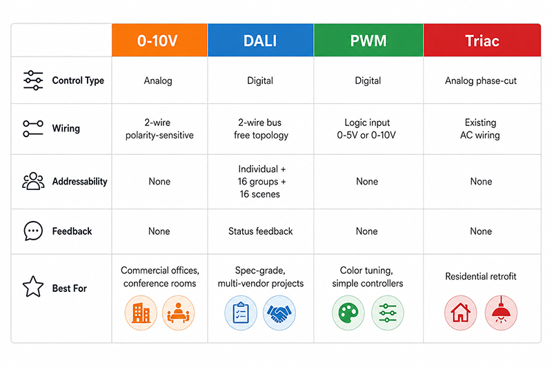
The choice of dimming protocol is a fundamental design decision for LED lighting OEMs. 0–10V provides simple, reliable analog dimming for commercial applications. DALI offers digital addressing, grouping, and feedback for specification-grade projects. PWM is useful for simple controllers and color-tunable systems. Triac dimming serves the retrofit market but presents compatibility challenges. Each protocol has distinct electrical characteristics, wiring requirements, and trade-offs that should be evaluated against the target market and installation requirements. Dedicated constant-current LED drivers with integrated dimming interfaces are available from specialized lighting driver manufacturers.
Related Resources
🔌 Related Products
🏭 Related Applications
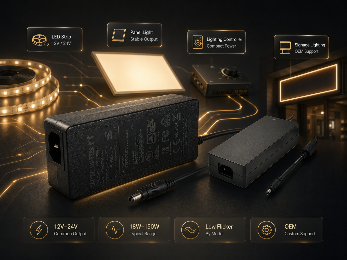

Industrial Control Power Solutions
Power solutions for PLC, CNC, servo and automation equipment
📖 Related Guides
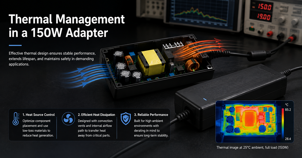
Thermal Management in a 150W Adapter
Fanless thermal management in a compact 150W adapter
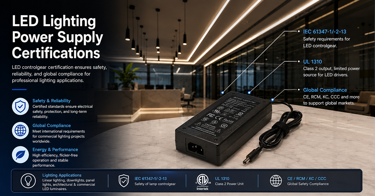
LED Lighting Power Supply Certifications
LED controlgear certification: IEC 61347-1/-2-13, UL 1310, global compliance
✅ Related Certifications