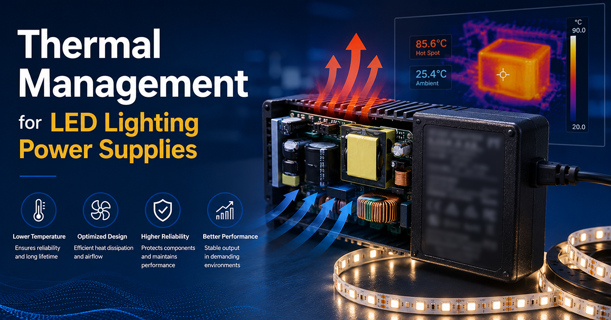
Thermal management is one of the most critical factors determining LED lighting system reliability. The power supply (LED driver) and the LED array are both heat sources within the luminaire, and the driver’s operating temperature directly affects its efficiency, output capacity, and service life. Unlike general-purpose power adapters installed in ventilated environments, LED drivers are often enclosed inside sealed luminaires where internal temperatures can significantly exceed the room ambient.
This guide covers the thermal management considerations for power supplies used in LED lighting systems: derating behavior, the relationship between temperature and capacitor lifetime, the effect of luminaire enclosure design, and practical thermal management strategies for OEMs.
Understanding Derating in LED Power Supplies
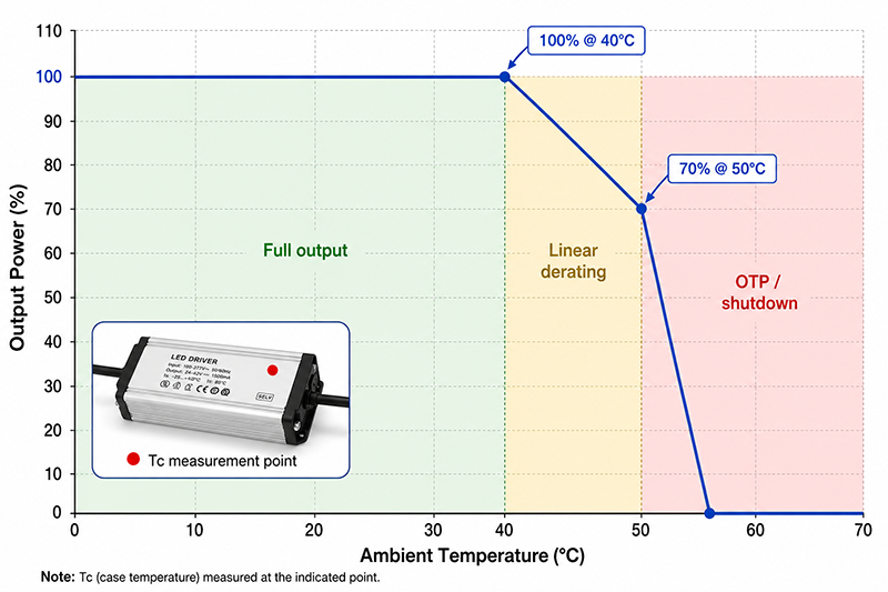
All power supplies reduce their rated output capacity as ambient temperature increases. This behavior, known as derating, is a protective measure that keeps internal component temperatures within their specified limits.
Derating Curve Characteristics
A typical derating curve specifies the maximum output power or current as a function of ambient temperature. For a driver rated for 100W output at up to 40°C ambient:
- 100% output from 0°C to 40°C
- Linear derating from 100% at 40°C to 70% at 50°C
- Further derating or shutdown above 50°C
The exact derating curve is model-specific and depends on the driver’s design, component selection, and enclosure construction. The driver’s datasheet should be consulted for the specific derating behavior.
Case Temperature (Tc) Point
Driver manufacturers specify a maximum case temperature (Tc) measured at a defined location on the driver enclosure. This is the temperature that must not be exceeded during operation. The Tc measurement point is chosen to represent the hottest accessible surface of the driver, which correlates with internal component temperatures.
Key points about Tc:
- Tc is measured at a specific location marked on the driver label or specified in the datasheet
- Exceeding Tc may trigger overtemperature protection (OTP) or reduce component lifetime
- Tc is not the same as ambient temperature—it accounts for self-heating
- The difference between Tc and ambient temperature depends on the driver’s efficiency, power level, and enclosure thermal resistance
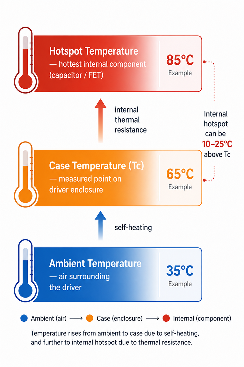
Ambient Temperature vs Hotspot Temperature
These are different measurements that should not be confused:
- Ambient temperature: The air temperature surrounding the driver
- Case temperature (Tc): The temperature at a defined point on the driver enclosure
- Hotspot temperature: The internal temperature of the hottest component (typically the electrolytic capacitor or switching FET)
The driver’s internal hotspot temperature can be 10–25°C above Tc, depending on the thermal design and power level.
Why This Matters
- A driver rated for 50°C ambient but installed inside a sealed outdoor luminaire exposed to direct sunlight may experience internal ambient temperatures of 60–70°C, exceeding the driver’s derating threshold.
- Operating a driver above its derating temperature reduces output capacity. A driver rated for 100W may deliver only 70W at 50°C ambient, potentially causing the luminaire to under-perform.
- The difference between ambient and Tc is load-dependent. A driver operating at 50% load runs cooler than one at 100% load, which affects the margin to the Tc limit.
OEM Actions
- Measure or estimate the internal ambient temperature of the luminaire during worst-case conditions (maximum external ambient + solar gain + LED self-heating + driver self-heating).
- Select a driver whose derating curve provides adequate output at the expected internal ambient temperature.
- Verify that the driver’s Tc specification is not exceeded under worst-case operating conditions by measuring Tc in a thermal chamber test.
Capacitor Lifetime and Temperature
The electrolytic capacitors inside the LED driver are typically the components that determine the driver’s useful life. Their lifetime is strongly dependent on operating temperature.
Lifetime Estimation
Capacitor manufacturers specify lifetime at a rated temperature (typically 105°C or 85°C) under specified ripple current and voltage conditions. The 10°C lifetime-doubling rule is a common engineering approximation: for every 10°C reduction in core temperature, the capacitor’s expected lifetime approximately doubles, and for every 10°C increase, it halves. This approximation is subject to the manufacturer’s lifetime model, ripple current, voltage stress, and actual core temperature.
Example (illustrative)
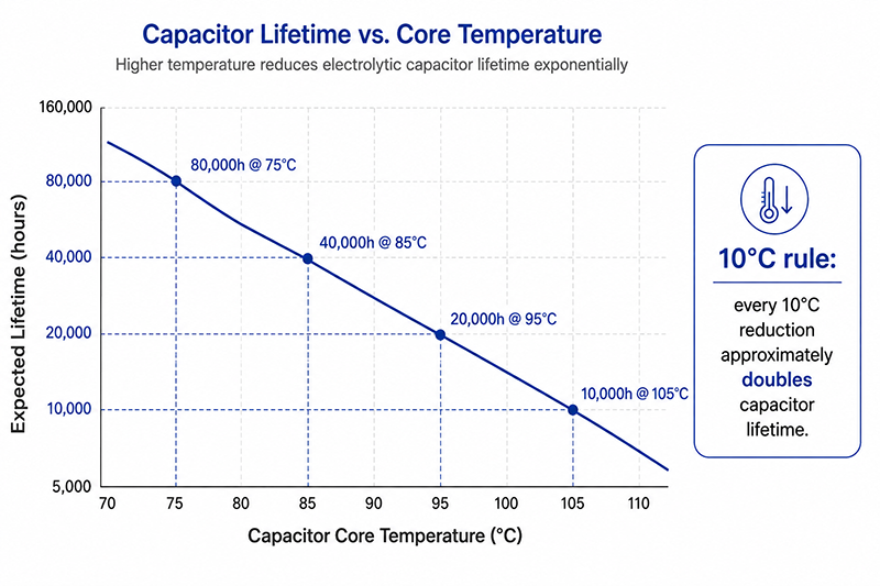
A capacitor rated for 10,000 hours at 105°C:
- At 95°C core temperature: ~20,000 hours (2×)
- At 85°C core temperature: ~40,000 hours (4×)
- At 75°C core temperature: ~80,000 hours (8×)
These figures are illustrative and should be verified against the specific capacitor manufacturer’s data.
Factors affecting capacitor temperature
- Ripple current: Higher ripple current increases internal heating in the capacitor. Each capacitor has a maximum rated ripple current.
- Proximity to other heat sources: Capacitors located near the switching FET, transformer, or heatsink experience higher temperatures.
- Airflow and enclosure: Sealed enclosures with no airflow increase capacitor temperature compared to ventilated designs.
Lifetime vs MTBF
Capacitor lifetime (the expected operating time before the capacitor degrades beyond its specified parameters) is related to but distinct from the driver’s MTBF (Mean Time Between Failures). MTBF is a statistical reliability metric calculated from component failure rates. It is not the expected lifespan of a specific unit. MTBF data may be available depending on model and calculation methodology.
Why This Matters
- Capacitor lifetime is the dominant wear-out mechanism in most LED drivers. Driver lifespan is typically specified at a defined Tc, not at ambient temperature.
- A driver rated for 50,000 hours at Tc=70°C will have a very different lifetime at Tc=85°C. The actual lifetime depends on the operating temperature in the specific installation.
- Using 105°C-rated capacitors instead of 85°C-rated capacitors provides a substantial lifetime margin at the same operating temperature, or allows higher operating temperature for the same lifetime target.
OEM Actions
- Request capacitor lifetime data from the driver manufacturer, specified at the expected Tc for your application.
- For luminaires designed for long service life (50,000+ hours), select drivers with 105°C-rated capacitors.
- Consider the ripple current contribution to capacitor heating when selecting the driver. Higher ripple current at the driver output increases capacitor core temperature beyond the case temperature.
Enclosure Effects and Thermal Design Strategies
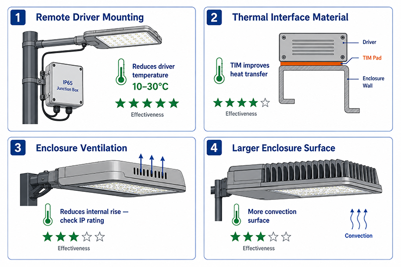
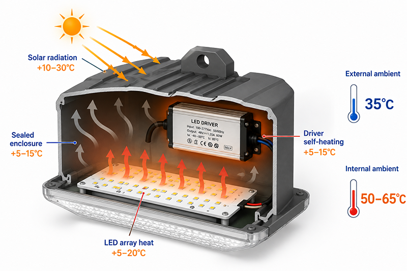
The luminaire enclosure design significantly affects the driver’s operating temperature. The enclosure traps heat from both the LED array and the driver, raising the internal ambient temperature above the external ambient.
Enclosure Temperature Rise Factors
| Factor | Typical Temperature Rise | Mitigation |
|---|---|---|
| Solar radiation on outdoor enclosure | 10–30°C above ambient | Reflective coating, shade, light-colored enclosure |
| LED array heat (30–40% of input power) | 5–20°C inside enclosure | Thermal management of LED board, heat sinking |
| Driver self-heating (efficiency-dependent) | 5–15°C above internal ambient | Efficient driver, thermal management inside driver |
| Sealed enclosure (no ventilation) | 5–15°C internal rise vs ventilated | Larger enclosure, external heatsink, remote driver mounting |
| Dark-colored enclosure in sunlight | 5–10°C additional vs light color | Light-colored or reflective enclosure finish |
Thermal Management Strategies
| Strategy | Description | Effectiveness | Trade-off |
|---|---|---|---|
| Remote driver mounting | Driver mounted outside luminaire enclosure | Reduces driver temperature by 10–30°C | Additional enclosure and wiring cost |
| Thermal interface material (TIM) | Thermal pad or gap filler between driver and enclosure | Improves heat transfer to enclosure surface | Material cost; requires good contact pressure |
| Envelope ventilation | Vents or openings in luminaire enclosure | Reduces internal temperature rise | Reduces IP rating; may allow dust/moisture ingress |
| Larger enclosure surface area | More surface area for convective heat transfer | Reduces internal and driver temperature | Larger luminaire size; aesthetic and cost constraints |
| Driver selection with higher efficiency | Lower internal losses = less heat | 1–2% efficiency improvement = 10–30% less heat in driver | May increase driver cost |
Remote Driver Mounting
Why This Matters
- The driver’s operating temperature is determined not just by the driver’s own losses but by the entire thermal environment: solar gain, LED heat, and enclosure ventilation.
- A 10°C reduction in driver operating temperature can approximately double the capacitor lifetime, making thermal management one of the most cost-effective reliability improvements.
- Remote driver mounting, while adding cost, can be the most effective thermal solution for high-temperature or outdoor installations where driver lifetime is critical.
OEM Actions
- During luminaire design, model or measure the internal ambient temperature near the driver location under worst-case conditions (maximum external ambient, full LED power, maximum driver load).
- Evaluate the trade-offs between remote driver mounting, enclosure ventilation (if IP rating permits), and higher-efficiency driver selection.
- Include thermal testing in the product validation plan: measure driver Tc and internal ambient temperature under worst-case conditions to verify derating margin and lifetime expectations.
Useful Links
Q: What is the typical lifetime of an LED driver at its rated operating temperature?
A: Driver lifetime is primarily determined by electrolytic capacitor lifetime and is specified at a defined case temperature (Tc). A driver rated for 50,000 hours at Tc=70°C will have a different lifetime at higher or lower case temperatures. Lifetime figures should be verified from the manufacturer’s datasheet and are model-dependent.
Q: Can I place the LED driver outside the luminaire to reduce thermal stress?
A: Yes, remote driver placement is a common strategy for high-temperature or sealed luminaire designs. The driver is housed separately (typically in an IP65 junction box or raceway) where the ambient temperature is lower than inside the luminaire. This improves driver lifetime but adds installation complexity and cost.
Q: How much does the internal temperature of a sealed luminaire rise above ambient?
A: The temperature rise can be 10–30°C above ambient, depending on LED power, driver efficiency, enclosure size, material, color, and solar exposure. For a 100W LED luminaire in a sealed enclosure at 35°C ambient, the internal temperature may reach 50–65°C. This should be verified through thermal measurement during product development.
Conclusion
Thermal management is a critical design consideration for LED lighting power supplies. Derating behavior, capacitor lifetime, and luminaire enclosure design all affect the driver’s operating temperature and service life. The key strategies for OEMs are: selecting a driver with appropriate derating for the expected internal ambient temperature, verifying the Tc margin through thermal testing, understanding the capacitor lifetime at the expected operating temperature, and evaluating enclosure and mounting strategies to reduce driver temperature. Attention to thermal management at the design stage is one of the most effective ways to improve LED luminaire reliability.
YHYadapter product positioning: YHYadapter provides regulated constant-voltage (CV) AC/DC power adapters (desktop, wall plug, open frame). Thermal management guidance in this guide applies to CV adapter integration in LED systems; dedicated constant-current LED drivers with luminaire-specific thermal design are available from specialized lighting driver manufacturers.
Related Resources
🔌 Related Products
🏭 Related Applications
Industrial Control Power Solutions
Power solutions for PLC, CNC, servo and automation equipment
📖 Related Guides
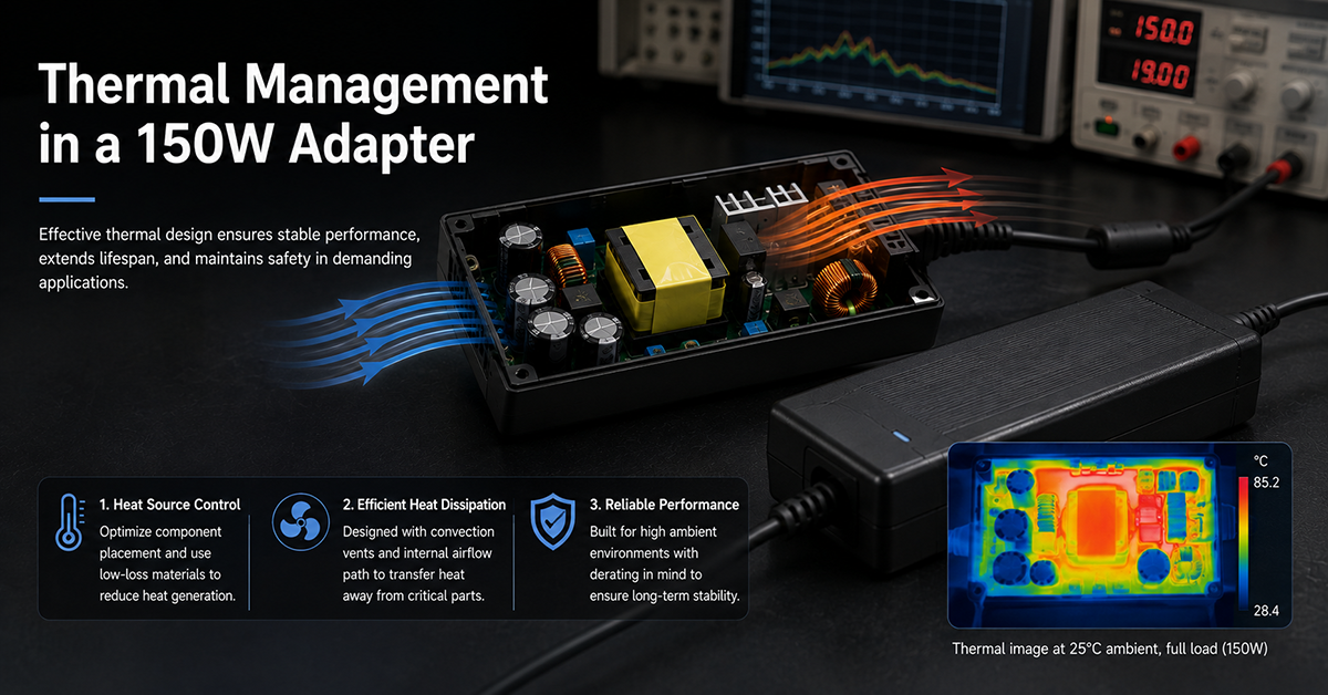
Thermal Management in a 150W Adapter
Fanless thermal management in a compact 150W adapter
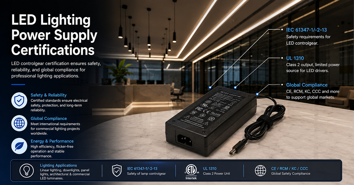
LED Lighting Power Supply Certifications
LED controlgear certification: IEC 61347-1/-2-13, UL 1310, global compliance
✅ Related Certifications