
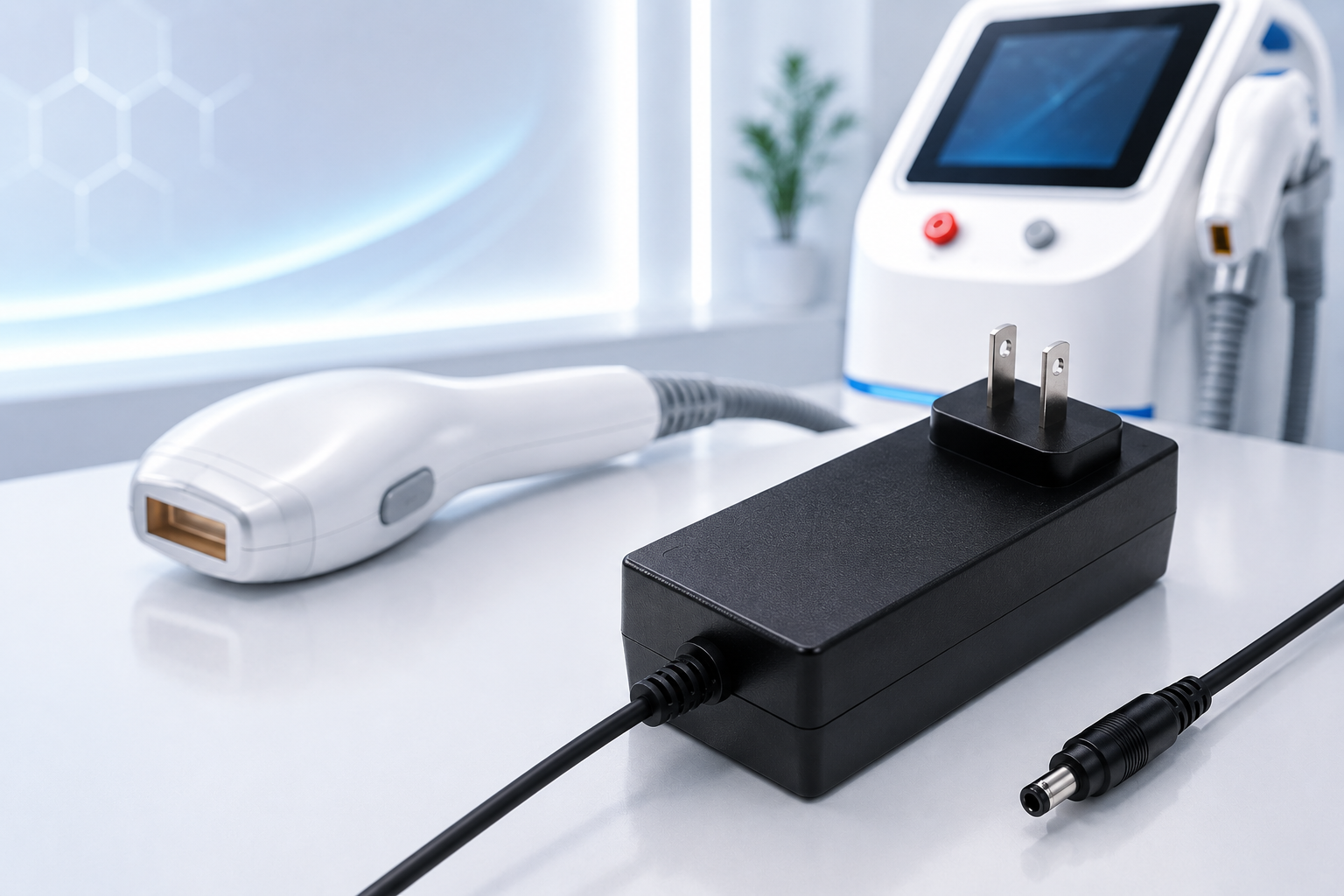
IPL (Intense Pulsed Light) hair removal devices are among the most common medical aesthetic products that require IEC 60601-1 certified power adapters when classified as medical electrical equipment — a determination based on intended use, therapeutic claims, and target market. These devices use high-voltage capacitor banks to discharge pulsed light through a handpiece, and the power adapter’s role is to charge the capacitor bank between pulses with stable, controlled output.
Unlike continuous-load applications, IPL systems draw power in repeated charge-discharge cycles. This pulsed-load profile imposes specific requirements on the power adapter: the average power draw determines the repetition rate, the peak current capability affects charge time, and the output stability directly impacts treatment consistency. For OEM manufacturers designing IPL platforms, selecting the correct power adapter affects device performance, certification timeline, and production cost.
This guide covers the electrical requirements of IPL hair removal systems, the power adapter specifications that matter, IEC 60601-1 compliance considerations specific to pulsed-light devices, and integration best practices for OEM design teams.
Understanding IPL Device Power Architecture
An IPL hair removal device consists of three main electrical subsystems: the power adapter (AC-DC converter), the capacitor bank (energy storage), and the flashlamp driver (pulse discharge). The power adapter charges the capacitor bank to a target voltage—typically 300VDC to 1000VDC depending on the device design—through a DC-DC boost converter or flyback topology.
The charge cycle operates in a repeating sequence:
1. Capacitor bank is depleted after a flash pulse 2. Power adapter delivers current to recharge the capacitor 3. When the capacitor reaches the set voltage, charging stops 4. Device signals “ready” for the next treatment pulse 5. Cycle repeats at the operator’s firing rate
The key design parameter is the duty cycle: the ratio of charge time to total cycle time. A typical IPL device may deliver pulses at 1–3 second intervals. If the capacitor bank is 1000µF charged to 600V (stored energy = ½ × C × V² = 180J), and the power adapter delivers 120W (e.g., 24V at 5A output), the charge time is approximately:
- Energy per pulse: 0.5 × 1000µF × (600V)² = 180J
- Power available: 120W at assumed 85% boost converter efficiency = 102W
- Minimum charge time: 180J / 102W ≈ 1.8 seconds
This means a 120W adapter can support approximately 0.5 pulse-per-second (1.8s charge + margin). A 150W adapter reduces charge time to approximately 1.4 seconds, enabling a faster treatment pace.
Why This Matters
- The adapter’s continuous output power directly limits the treatment speed of the IPL device—higher power enables faster repetition rates
- Under-specifying the adapter results in slow charge times that frustrate operators and reduce clinical throughput
- Over-specifying adds cost and physical size to the device without proportional clinical benefit
What OEMs Should Do Now
- Calculate the energy-per-pulse requirement based on the flashlamp and capacitor specifications
- Derive the minimum adapter power rating from the target repetition rate and system efficiency
- Add 20–30% margin to account for capacitor aging, temperature effects, and boost converter losses
Useful Links
Application page: Medical Aesthetic Power Solutions →
Product page: YHY-12005000 Medical Desktop Adapter →
Q: Why can’t an IPL device use a standard 24V industrial power adapter?
A: Standard industrial power adapters (IEC 62368-1) lack the medical-grade isolation (2×MOPP) and leakage current limits (<100µA for BF-type) required for patient-contact aesthetic devices per IEC 60601-1. Additionally, the pulsed-load profile may cause voltage droop or instability in adapters not designed for capacitor-charging applications.
Q: What is the typical power range for IPL device adapters?
A: Most professional IPL hair removal platforms use adapters in the 120W to 240W range. Portable home-use devices may use 65W to 100W adapters with lower energy-per-pulse and longer charge times.
IEC 60601-1 Requirements Specific to IPL Power Adapters
IPL hair removal devices within IEC 60601-1 scope are typically classified as Type BF (Body Floating) applied parts, because the handpiece makes conductive contact with the patient’s skin through the treatment window, and the light pulse is delivered through optical coupling. This classification determines the isolation and leakage current requirements for the power adapter. Medical-grade adapter options are available by model — e.g., YHY-12005000 (12V/5A) and YHY-24002500 (24V/2.5A) carry IEC/EN 60601-1 certification (certificate CTC20231117SC01/EC).
The critical IEC 60601-1 requirements for IPL adapter selection:
| Requirement | Specification | Why It Matters for IPL |
|---|---|---|
| Patient leakage current | ≤100µA (normal), ≤500µA (single fault) | Direct skin contact via handpiece |
| 2×MOPP isolation | ≥8mm creepage at 250VAC | Protects patient during high-voltage capacitor discharge |
| Dielectric strength | 4000VAC primary-to-secondary | Must withstand combined mains + capacitor circuit insulation stress |
| Earth leakage current | ≤500µA | Grounding integrity for portable aesthetic platforms |
| EMC immunity (IEC 60601-1-2) | ±8kV contact ESD, ±15kV air | Handpiece used in varied clinical environments with static sources |
Why This Matters
- Even if the IPL device has its own internal DC-DC isolation, the power adapter must independently meet 2×MOPP—two layers of isolation are better than assumed safety stacking
- Certification labs will test the complete system: power adapter connected to the IPL device in its operating configuration
- Using a non-certified adapter forces the device manufacturer to justify alternative isolation strategies, adding certification time and cost
- Specify power adapters with published IEC 60601-1 3rd Edition certification for BF-type equipment
- Request leakage current data at both nominal and 110% rated voltage to ensure compliance across mains variation
- Verify that the adapter’s ESD immunity level meets the medical standard (±8kV contact, ±15kV air) for operator-touched equipment
Useful Links
Related article: IEC 60601-1 Certification Guide →
Product page: YHY-12005000 Medical Desktop Adapter →
Q: Does the power adapter need certification for the full IPL operating environment including the boost converter’s high voltage?
A: The power adapter certification covers the AC-DC conversion stage up to its DC output terminals. The downstream high-voltage section (boost converter, capacitor bank) is covered by the end product’s IEC 60601-1 evaluation. The adapter’s 2×MOPP isolation to ground is the prerequisite.
Q: What certification documents should be provided for the adapter in an IPL device filing?
A: CB test certificate and report (IEC 60601-1 Edition 3.1), leakage current test report, dielectric strength test report, IEC 60601-1-2 EMC test report, and the manufacturer’s ISO 9001:2015 certificate. All document numbers must match the specific adapter model being used.
Power Adapter Output Voltage and IPL Capacitor Charging
The power adapter output voltage for IPL systems is typically in the 24V–48V range, which is then boosted internally to 300–1000VDC for the capacitor bank. The choice of adapter output voltage affects the boost converter design and overall system efficiency.
Common adapter voltage configurations for IPL devices:
| Adapter Output | Typical Boost Input | Application |
|---|---|---|
| 24V | 20–28V range | Common for 150–300W systems |
| 36V | 30–40V range | Higher-power systems (200W+), better boost efficiency from higher input |
| 48V | 42–54V range | High-power professional platforms, reduced boost ratio improves efficiency |
Why This Matters
- Higher adapter output voltage typically yields better end-to-end system efficiency (0.5–2% improvement per 12V step-up)
- The boost converter components (inductor, MOSFET, diode) can be smaller and less expensive with a higher input voltage
- However, 48V adapters are less common in the medical-certified segment—where confirmed medical certification is typically ≤65W (e.g., YHYadapter’s YHY-080~560 series), with higher-power options available by model
- Evaluate the trade-off between adapter availability (24V is most widely available in medical-certified lines) and boost efficiency (48V offers 1–3% better system efficiency)
- Request efficiency curves from the adapter manufacturer at the expected load profile (average capacitive charge current, not resistive continuous load)
- Consider whether a custom output voltage (e.g., 28V, 32V) fits your design—medical adapter manufacturers often offer OEM voltage customization within the same certified platform
Useful Links
Product page: YHY-12005000 Medical Desktop Adapter →
Related article: Choosing Power Adapters for Medical Aesthetic Devices →
Q: Can I use a 48V adapter if the available medical-certified models only go up to 150W?
A: Yes, if the power rating meets your charge time requirement. Medical certification coverage is confirmed by model — YHYadapter’s confirmed IEC 60601-1 range is the YHY-080~560 series (8–56V, ≤5A, ≤65W, Class II), and higher-power medical options are available by model. Confirm the certification coverage for your specific model and target market with the manufacturer.
Q: Does the adapter output voltage stability matter for IPL charging?
A: The adapter output feeds a regulated boost converter, so moderate voltage variation (±5%) is acceptable as long as the boost converter’s input range covers it. However, excessive ripple (>200mVpp) can interfere with the boost converter’s control loop. Request ripple specifications at full load.
Form Factor and Thermal Considerations for IPL Devices
IPL hair removal devices range from compact handheld units (typically 65–100W adapter) to rolling-cart professional platforms (150–240W adapter). The power adapter form factor must match the device’s industrial design and thermal environment.
Desktop adapters are the most common choice for IPL devices above 100W. The external form factor allows the thermal load—up to 15–25W of heat dissipation from the adapter at full load—to be managed outside the device enclosure. This simplifies the aesthetic device’s own thermal design and reduces internal airflow requirements.
Wall-plug adapters are suitable for compact home-use IPL devices under 75W, where the adapter plugs directly into a wall outlet and the device itself is a handheld unit with minimal internal thermal management. However, wall-plug adapters have less surface area for heat dissipation and may operate at higher internal temperatures (typically 70–85°C case temperature at full load) compared to desktop adapters (55–65°C).
Thermal design considerations:
- Desktop adapters can be positioned away from the device or placed in a well-ventilated area
- Wall-plug adapters must be plugged directly into a wall outlet, and the outlet’s local ambient temperature adds to the adapter’s thermal load
- For IPL devices operating in warm environments (salons, clinics), ambient temperatures of 35–40°C are common—verify adapter derating curves at these temperatures
- The adapter’s AC input cable length affects voltage drop: for 150W at 100VAC, a standard 1.8m 18AWG cable drops approximately 0.5V (0.5%), which is negligible
Why This Matters
- Desktop adapters offer better thermal performance and longer service life in professional IPL platforms that operate 6–10 hours per day
- For compact home-use devices, wall-plug adapters provide a cleaner aesthetic but require careful thermal derating verification
- The IP rating of the adapter (typically IP20 for indoor use) should match the clinical environment—salon environments with proximity to water require IP22 or better
What OEMs Should Do Now
- Determine the expected ambient temperature at the adapter’s installation location—salon and clinic environments can reach 35–40°C
- Request the derating curve from the adapter manufacturer showing maximum output power versus ambient temperature
- For desktop deployments, plan for cable management—the adapter’s DC cable typically ranges from 1.2m to 1.8m
Useful Links
Product page: YHY-12005000 Medical Desktop Adapter →
Related article: Power Supply Thermal Management Design Considerations →
Q: Can an IPL power adapter be mounted inside the device enclosure?
A: This is discouraged for medical aesthetic devices. An internal AC-DC converter would require the entire device to meet IEC 60601-1 enclosure leakage current and thermal requirements, plus the internal heat from the power supply adds to the device’s cooling load. External adapters simplify certification.
Q: What is the typical operating life of a medical adapter in continuous IPL use?
A: Medical-grade adapters with electrolytic capacitors rated at 105°C and ≥5000-hour life at rated temperature typically provide 3–5 years of continuous daily use (8 hours/day, 5 days/week). The adapter’s cooling (natural convection) and ambient temperature are the primary factors affecting lifespan.
EMC Compliance for IPL Systems with Power Adapters
IPL hair removal systems contain high-energy pulsed circuits generating significant electromagnetic interference. The power adapter must maintain proper operation and emissions compliance under the combined interference from the flashlamp discharge circuit, which produces broadband noise from DC to several hundred MHz.
Per IEC 60601-1-2 Edition 4, IPL devices with power adapters must meet:
- CISPR 11 Group 1 Class B radiated and conducted emissions
- ±8kV contact / ±15kV air ESD immunity (IEC 61000-4-2)
- ±2kV electrical fast transient immunity (IEC 61000-4-4)
- ±1kV differential / ±2kV common mode surge immunity (IEC 61000-4-5)
- Radiated RF immunity: 3V/m from 80MHz to 2.7GHz (IEC 61000-4-3)
The flashlamp discharge circuit is a particular interference source. When the capacitor bank discharges through the flashlamp, the current pulse can couple back into the power adapter’s DC output lines through the shared ground path. This coupled interference can cause the adapter’s control IC to malfunction, the output voltage to fluctuate, or—in severe cases—the adapter to enter hiccup or latch-off protection mode.
Mitigation strategies:
- Ferrite beads on the adapter’s DC output cable (common-mode suppression)
- Additional filtering (Pi-filter) at the IPL device’s power input
- Shielding the flashlamp driver and capacitor bank within the device enclosure
- Keeping the adapter’s DC cable physically separated from the flashlamp driver wiring (minimum 50mm separation)
Why This Matters
- EMC testing of the complete IPL system (device + adapter) is required for IEC 60601-1-2 certification—the adapter certified alone does not guarantee the system passes
- Flashlamp interference causing adapter malfunction during EMC testing is a common failure mode in IPL certification
- Adding filtering or ferrite suppression after certification requires retesting—design it in from the start
What OEMs Should Do Now
- During the design phase, test the power adapter with the IPL device operating at maximum pulse energy and frequency to identify interference coupling paths
- Include the adapter’s EMC test report in the system-level EMC planning—specifically the radiated immunity and ESD performance data
- Prototype the DC input filtering (common-mode choke + X-capacitor + Y-capacitor) before printed circuit board layout is finalized
Useful Links
Related article: IEC 60601-1 Certification Guide →
Application page: Medical Aesthetic Power Solutions →
Q: Does the power adapter need separate EMC testing for the IPL application?
A: The adapter is typically tested as a component to IEC 60601-1-2 in its standalone configuration. The complete IPL system then undergoes system-level EMC testing. However, the adapter’s EMC performance data informs the system-level filter design and helps predict certification outcomes.
Q: Can a standard medical adapter and a standard consumer IPL adapter be EMC-compatible with the same IPL device?
A: Not necessarily. Different adapters have different input filter designs and control loop responses, which interact with the IPL device’s interference profile. An adapter that performs well with one IPL design may exhibit issues with another. System-level EMC testing is always required.
Conclusion
Power adapter selection for IPL hair removal devices requires understanding the pulsed-load power architecture, IEC 60601-1 certification requirements specific to Type BF aesthetic equipment, and the thermal and EMC integration considerations that affect overall system performance. The adapter’s output power directly determines treatment speed, while its certification status determines regulatory pathway.
For OEM manufacturers, the practical approach is to select a medical-certified adapter with published 2×MOPP isolation and ≤100µA leakage current, match the power rating to the target charge time with appropriate margin, and plan for system-level EMC testing that validates the adapter-device interface.