
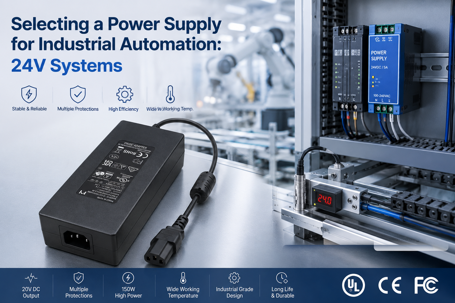
Industrial automation equipment is often designed for continuous operation, where unstable power or unexpected power supply failure can result in equipment faults, communication interruptions, and costly downtime. 24V DC is widely used across industrial control systems, powering equipment such as HMI panels, industrial PCs, communication devices, sensors, controllers, and other automation peripherals.
For equipment powered by an external AC/DC power supply, selecting the right 24V adapter involves more than matching voltage and wattage. Engineers must also consider continuous and peak load requirements, startup current, cable voltage drop, thermal performance, protection behavior, connector reliability, operating environment, and long-term stability.
This guide explains the key considerations for selecting 24V external power supplies for industrial automation equipment, including load and power sizing, startup and peak-current requirements, voltage drop over DC output cables, thermal and reliability considerations, connector selection, and safety and EMC requirements for different target markets.
How Do You Profile the 24V Load of Industrial Automation Equipment?
Industrial automation equipment may combine controllers, HMI panels, sensors, communication devices, and actuators with very different current characteristics. Before selecting a 24V external power supply, engineers should calculate both the continuous load and any startup or transient load expected during operation.
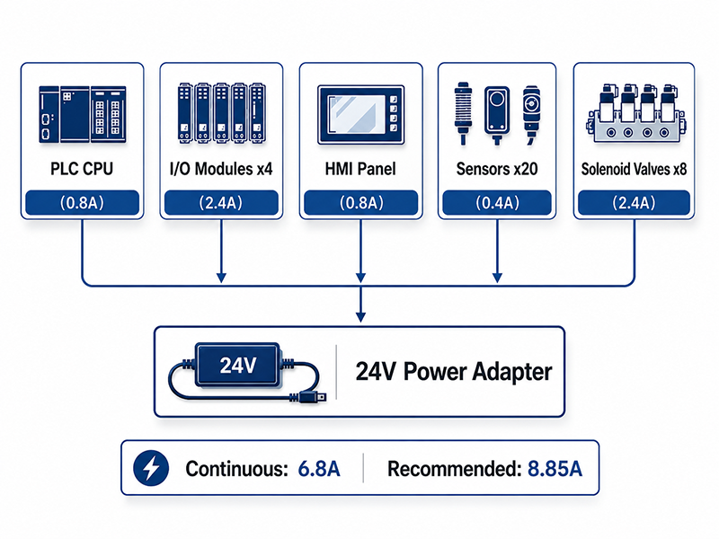
Typical 24V Loads
| Device Type | Typical Current | Design Consideration |
|---|---|---|
| PLC / Controller | 0.3–0.8A | Depends on CPU, integrated I/O, and configuration |
| Digital I/O Module | 0.05–0.5A+ | Include current drawn by connected field loads where applicable |
| Analog I/O Module | 0.1–0.3A | Depends on channel count and connected devices |
| HMI Panel (7–10″) | 0.5–1.2A | Display size, backlight, processor, and interfaces affect consumption |
| Proximity Sensor | 0.01–0.03A each | Multiply by the number of simultaneously powered sensors |
| Solenoid Valve | 0.1–0.5A each | Check pull-in, holding, and simultaneous activation requirements |
| Small DC Motor / Actuator | 0.5–3A+ | Startup or stall current can be substantially higher than normal running current |
Values are illustrative only. Always use the equipment manufacturer’s rated and peak-current specifications for final power-system design.
Example Load Calculation
Consider a compact automation device powered from 24V DC:
- Controller: 0.6A
- HMI: 0.8A
- 10 proximity sensors: 0.2A
- Communication and I/O electronics: 0.5A
- Four actuators / solenoids during normal operation: 1.2A
Estimated continuous load:
0.6 + 0.8 + 0.2 + 0.5 + 1.2 = 3.3A
At 24V:
24V × 3.3A = 79.2W
If a 25% design margin is used as an initial engineering allowance:
3.3A × 1.25 = 4.13A
A 24V / 5A (120W) external power supply could therefore provide suitable continuous-power headroom, provided its transient capability, thermal performance, and operating conditions also meet the application requirements.
Why This Matters
- The actual 24V load can be higher than the initial estimate when field devices, communication modules, actuators, or future expansion are not included in the power budget.
- Output modules also require special attention: the module’s own consumption and the current delivered to connected loads may need to be accounted for separately according to the PLC architecture.
- A reasonable design margin can provide additional headroom for component tolerances, operating conditions, load variation, and future expansion—but the appropriate margin should be determined for the specific system rather than applied as a universal percentage.
What OEMs Should Do Now
- Create a load inventory that records:Device → Quantity → Continuous Current → Peak Current → Simultaneous Operation → Notes
- Separate continuous load from startup and transient load. The power supply must support the steady-state requirement while also tolerating the actual transient profile without excessive voltage drop, protection shutdown, or unstable restart behavior.
- Also review the startup sequence. If controllers, displays, sensors, motors, and actuators energize simultaneously, the initial peak demand may be significantly higher than the normal operating load.
Q: Should PLC internal or backplane power be included in the external 24V power budget?
A: It depends on the PLC architecture. Some PLC systems use an integrated or dedicated power supply for the CPU and backplane, while others accept 24V DC directly and distribute power internally. Field-side I/O, sensors, actuators, and HMI equipment may also have separate supply paths. Always follow the PLC manufacturer’s power-budget and wiring documentation.
Q: How much startup current should I allow?
A: There is no universal multiplier. Startup demand depends on the connected equipment. Input capacitors can produce short inrush pulses, motors can require substantially higher starting current, and solenoid coils may have different pull-in and holding characteristics.
Check the peak-current profile of the loads and compare it with the power supply’s specified overload, peak-current, and protection characteristics. If simultaneous startup exceeds the available capability, consider load sequencing, additional power headroom, or a power supply designed for the required transient load.
24V vs. 48V Architecture in Industrial Automation Equipment
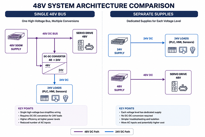
While 24V DC is widely used for industrial controls, sensors, HMI panels, communication equipment, and actuators, higher-power devices may operate at 48V DC or other voltage levels. Equipment combining both low-power control electronics and higher-power loads may therefore require a 24V architecture, 48V architecture, or mixed-voltage power system.
The choice should be based on total power, load distribution, cable length, voltage-drop limits, efficiency, component compatibility, and system reliability.
Why Consider 48V?
For the same output power, increasing the distribution voltage reduces the required current.
For example, at approximately 500W:
| Architecture | Current at 500W | Relative Current |
|---|---|---|
| 24V DC | ≈20.8A | 100% |
| 48V DC | ≈10.4A | 50% |
Lower current can reduce conductor requirements, connector stress, voltage drop, and resistive losses.
Because cable losses are proportional to I²R, reducing current by half can theoretically reduce resistive losses by approximately 75%, assuming the same conductor resistance.
This can make 48V attractive for higher-power equipment or applications where cable losses and current capacity become significant design constraints.
24V, 48V, or Mixed Voltage?
| Architecture | Best Suited For | Key Considerations |
|---|---|---|
| 24V System | PLCs, HMIs, sensors, control electronics, communication equipment, smaller actuators | Broad industrial compatibility and simpler integration |
| 48V System | Higher-power actuators, motors, communication equipment, and equipment designed around 48V input | Lower current for equivalent power and potentially lower distribution losses |
| Mixed 24V / 48V System | Equipment combining 24V controls with higher-power 48V loads | Requires separate supplies or DC-DC conversion and additional system-level design |
Separate Supplies vs. DC-DC Conversion
A mixed-voltage system can generally be implemented in two ways:
Separate Power Supplies
AC Input → 24V Supply → 24V Loads
AC Input → 48V Supply → 48V Loads
This approach can simplify voltage-domain separation and avoid conversion losses between the 48V and 24V sections.
48V Distribution with DC-DC Conversion
AC Input → 48V Supply → 48V Loads
↓
48V → 24V DC-DC → 24V Loads
This architecture can reduce current in the main distribution path but introduces an additional conversion stage.
The DC-DC converter must be evaluated for:
- Output power and peak load
- Conversion efficiency
- Thermal performance
- Input and output voltage range
- Protection behavior
- Isolation requirements
- EMC performance
- Operating environment
- Long-term reliability
Engineering Note
Higher voltage reduces current for the same power, but it does not automatically make 48V the better architecture.
If most equipment operates at 24V, a direct 24V supply may provide the simplest and most efficient solution. If a significant portion of the system requires higher power at 48V, a 48V or mixed-voltage architecture may reduce distribution current and improve overall system integration.
The final architecture should be selected based on the actual load profile and system requirements, rather than fixed thresholds for power, cable length, or percentage of 48V loads.
Why This Matters
- Requesting a voltage outside the platform’s capability requires a new transformer design, adding $3,000–8,000 in NRE (non-recurring engineering) costs and 4–8 weeks to the timeline.
- Modifying current output upward by more than 20% may change the thermal profile, requiring enclosure modifications or adding a heatsink — which affects size and certification.
- A well-scoped customization request that stays within the platform’s design margins can be delivered in 4–6 weeks with no NRE cost.
What OEMs Should Do Now
- Before selecting the power architecture, map each load by:Voltage → Continuous Power → Peak Power → Cable Length → Connector → Startup Behavior
- Then compare:24V Architecture vs. 48V Architecture vs. 24V + 48V Mixed Architecture
- Evaluate total system efficiency, wiring requirements, thermal performance, component count, reliability, compliance, and future expansion before selecting the final configuration.
Q: Can a 48V power adapter directly charge a 24V battery system?
A: No. A battery requires a charging system designed for its chemistry, voltage, charging profile, current limits, protection requirements, and battery-management architecture. A 48V power supply should not be connected directly to a 24V battery.
Where battery backup is required, use a dedicated charger or appropriately designed DC-DC charging stage matched to the battery system.
Q: Is 48V always more efficient than 24V?
A: No. Higher distribution voltage can reduce cable and connector losses because less current is required for the same power. However, additional DC-DC conversion, component selection, load characteristics, and operating conditions also affect total system efficiency.
The appropriate voltage architecture should therefore be evaluated at the system level, not from distribution voltage alone.
Useful Links
→ Desktop Adapter Series
→ Industrial Automation Power Solutions
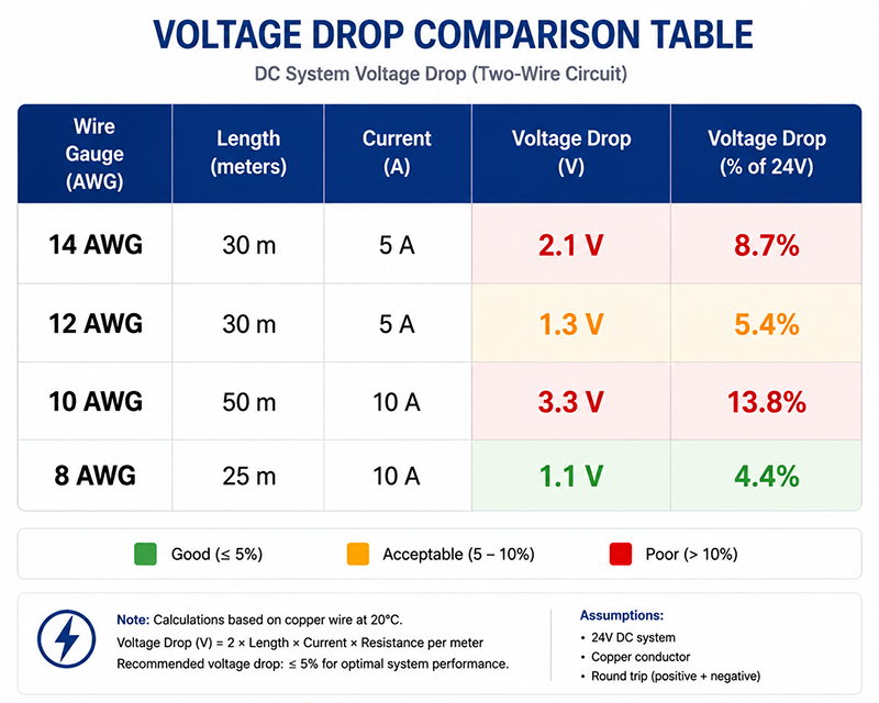
What Cable and Voltage Drop Considerations Apply to 24V Power Systems?
Voltage drop is an important consideration in 24V DC systems because even a relatively small loss in the cable reduces the voltage available at the equipment.
The actual voltage at the load depends on output current, conductor resistance, cable length, connector resistance, and the power supply output voltage. For industrial equipment, cable design should therefore be evaluated under maximum expected operating load rather than assumed from the nominal 24V rating.
Understanding Voltage Drop
For a two-conductor DC cable, voltage drop can be estimated as:
Vdrop = 2 × L × R × I
where:
- L = one-way cable length
- R = conductor resistance per unit length
- I = load current
The factor of 2 accounts for both the outgoing and return conductors.
As current or cable length increases, voltage drop increases. A larger conductor reduces resistance and therefore reduces both voltage drop and cable power loss.
Example: 24V Cable Voltage Drop
The following examples use approximate copper conductor resistance at 20°C and assume the stated distance is the one-way cable length.
| Load | Cable | One-Way Length | Approx. Voltage Drop | Approx. Drop |
|---|---|---|---|---|
| 24V / 5A | 14 AWG | 30m | ≈2.5V | ≈10.4% |
| 24V / 5A | 12 AWG | 50m | ≈2.6V | ≈10.8% |
| 24V / 10A | 10 AWG | 30m | ≈2.0V | ≈8.2% |
| 24V / 10A | 12 AWG | 20m | ≈2.1V | ≈8.7% |
Values are illustrative. Actual conductor resistance increases with temperature and can also be affected by cable construction, connectors, terminals, and manufacturing tolerances.
These examples show why long cable runs and higher currents can become problematic in a 24V system even when the power supply itself maintains accurate output regulation.
Why This Matters
- Voltage drop is proportional to:Vdrop = I × R while cable power loss is:Ploss = I² × R
- This means increasing current not only increases voltage drop but increases resistive power loss even more rapidly.
- The acceptable voltage drop should be determined from the actual input-voltage range of the powered equipment, including startup conditions, peak load, cable temperature, connector losses, and required design margin.
For External 24V Power Adapters
For equipment powered by an external AC/DC adapter, the most practical approach is usually to optimize the DC output cable rather than design around long-distance DC distribution.
Key variables include:
- Cable length
- Wire gauge
- Maximum continuous current
- Peak current
- Connector resistance
- Allowable voltage drop
- Cable temperature rise
Higher-current or longer-cable applications may require a larger conductor, shorter cable, lower-resistance connector, or a power supply configuration designed to compensate for the expected line loss.
Engineering Example
Consider a 24V / 5A industrial power adapter.
If the equipment requires a relatively long DC output cable, using a small conductor can produce excessive voltage drop at full load. Increasing the conductor size reduces resistance and helps maintain adequate voltage at the equipment input.
For this reason, cable length and AWG should be specified together with the output current—not selected independently.
Engineering Note
The power supply output may be 24.0V, but the equipment only receives the voltage remaining after cable and connector losses.
Always calculate or measure voltage at the load under the expected operating conditions. The allowable voltage drop should be based on the equipment manufacturer’s specified input-voltage range rather than a universal 3%, 5%, or 10% rule.
For applications requiring long-distance 24V distribution, multiple cabinets, or high branch currents, system-level power distribution should be evaluated separately from the external power adapter itself.
Useful Links
→ Desktop Adapter Series
→ How to Choose the Right Power Adapter
📞 CTA Block —— Designing a 24V automation system?
Contact our engineering team for power supply sizing assistance and distributed power architecture recommendations.
- Request a Quote → — Submit your requirements for a detailed quotation
- Talk to an Engineer → — Discuss technical specs with our design team
What Protection and Reliability Features Are Critical for Industrial 24V Supplies?
Industrial automation equipment often operates continuously and may experience startup surges, short circuits, overloads, elevated temperatures, and disturbances from the AC power network. A 24V power supply should therefore provide appropriate protection while maintaining stable operation under expected load and environmental conditions.
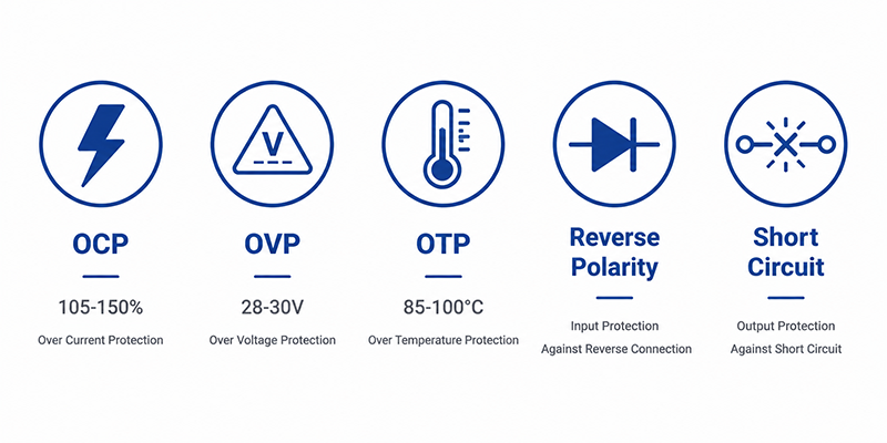
Core Protection Functions
| Protection | Purpose | Engineering Consideration |
|---|---|---|
| Overcurrent Protection (OCP) | Limits excessive output current during overload conditions | Trip threshold and recovery behavior should accommodate normal startup and peak loads without nuisance shutdown |
| Overvoltage Protection (OVP) | Prevents excessive output voltage from reaching connected equipment | Threshold should remain above normal regulation limits but below levels that could damage the load |
| Short-Circuit Protection (SCP) | Protects the supply and wiring during an output short circuit | The supply should safely limit or interrupt output and recover according to the intended application |
| Overtemperature Protection (OTP) | Prevents damage when internal temperatures exceed safe operating limits | Threshold and recovery behavior depend on component ratings, thermal design, and operating environment |
| Reverse / Backfeed Protection | Protects against unintended reverse current or polarity conditions where applicable | Particularly relevant to battery-backed, redundant, field-wired, or multi-source power systems |
Protection behavior is as important as the threshold itself. Depending on the application, the supply may use hiccup, constant-current, foldback, auto-recovery, or latching protection.
The appropriate strategy should be selected according to the load characteristics and system-level fault response.
Reliability Considerations
For industrial applications, reliability should be evaluated through more than the nominal output rating.
Key indicators may include:
- MTBF data, with the calculation method and operating temperature clearly specified
- High-temperature, long-life electrolytic capacitors with appropriate derating
- Thermal margin at continuous rated load
- Burn-in or production stress screening, where used by the manufacturer
- Component derating for voltage, current, power, and temperature
- Surge and transient immunity appropriate to the intended environment
- Protection verification under overload, short-circuit, and abnormal operating conditions
MTBF and Component Lifetime
MTBF is a statistical reliability estimate, not the expected lifetime or guaranteed service life of an individual power supply.
When comparing power supplies, OEMs should review the calculation methodology, operating temperature, load conditions, and assumptions behind the published MTBF value rather than comparing the headline number alone.
Capacitor specifications should be evaluated in the same way. A capacitor rated for thousands of hours at its maximum temperature can achieve substantially longer service life when operated at a lower actual temperature, making thermal design and component placement critical to long-term reliability.
Surge & EMC Immunity
Industrial environments may expose power supplies to electrical disturbances generated by switching equipment, motors, contactors, or the AC distribution network.
Testing such as IEC 61000-4-5 surge immunity can be relevant, but the required test level should be determined by the applicable product standard, installation environment, equipment category, and target market rather than treated as a universal industrial requirement.
Why This Matters
- Before approving a 24V power supply, define the required protection behavior for the application:Fault Type → Threshold → Response → Recovery → System Impact
- OEMs should also request relevant reliability and validation information, such as MTBF methodology, thermal test conditions, capacitor specifications, protection behavior, burn-in or production screening procedures, and applicable EMC immunity test results.
Engineering Note
A protection function is only effective when its threshold and response behavior match the actual load and system requirements.
For example, an OCP threshold that is too low may cause nuisance shutdown during actuator startup, while a threshold that is too high may provide insufficient protection during a sustained overload.
Likewise, whether OVP should latch or automatically recover depends on the system architecture and risk assessment. Critical equipment may benefit from a latched shutdown requiring deliberate intervention, while automatic recovery may be appropriate where temporary disturbances are expected and unattended recovery is desirable.
Redundancy and Parallel Operation Considerations
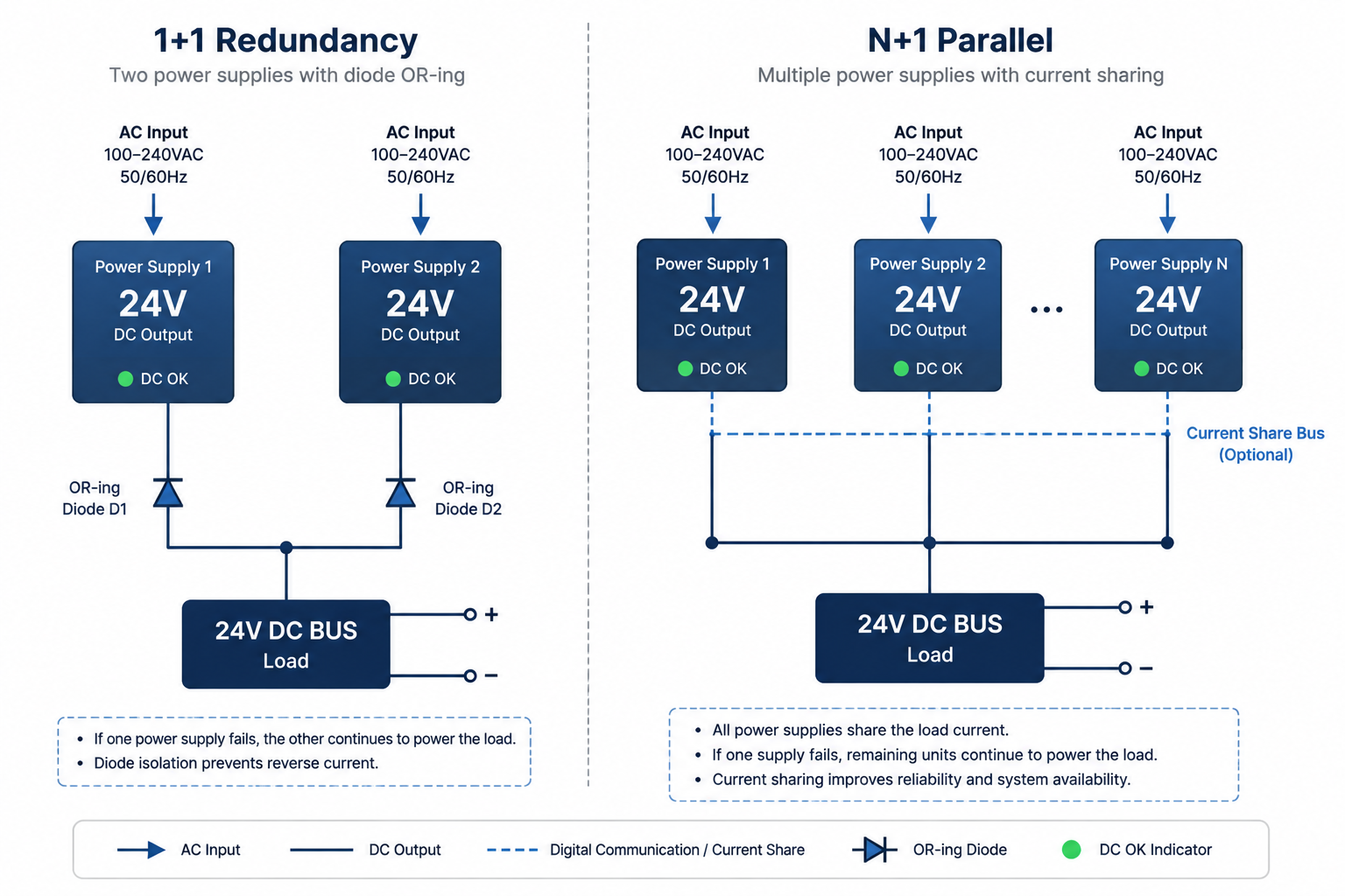
Critical automation equipment may require redundant power architecture to maintain operation if one power supply fails. Common approaches include 1+1 redundancy, where either supply can support the full load, and N+1 redundancy, where additional power capacity allows the system to continue operating after the loss of one supply.
1+1 Redundancy
In a 1+1 architecture, two power supplies are sized so that either unit can support the required load.
Power Supply A → Isolation / OR-ing → 24V Load
Power Supply B → Isolation / OR-ing → 24V Load
Output isolation prevents a fault or reverse-current condition in one supply from adversely affecting the other source.
Depending on the design, isolation may be implemented using OR-ing diodes, MOSFET-based ideal-diode circuits, external redundancy modules, or integrated reverse-current protection.
Any voltage drop and power loss introduced by the isolation stage should be included in the system power budget.
Parallel Operation
Parallel operation is different from simply connecting two power supplies together.
When multiple supplies are intended to share the load during normal operation, they should be specifically designed or approved for parallel operation and current sharing.
Without appropriate sharing control, small differences in output voltage can cause one supply to carry substantially more current than the other, potentially leading to thermal stress, protection activation, or reduced reliability.
| Architecture | Purpose | Key Requirement |
|---|---|---|
| 1+1 Redundancy | Maintain operation after one supply fails | Each supply can support the required load; appropriate output isolation |
| N+1 Redundancy | Provide fault tolerance in higher-power systems | Sufficient remaining capacity after one supply fails |
| Parallel Operation | Increase available output current or distribute load | Supplies must explicitly support parallel/current-sharing operation |
Monitoring & Fault Detection
For critical equipment, redundancy should also include a method of detecting when one power source has failed.
Useful monitoring functions may include:
- AC input status
- DC output status
- Power-good signal
- Alarm relay
- Overtemperature indication
- Communication or remote monitoring interface
Without fault monitoring, a redundant system may continue operating on the remaining supply while the failed unit goes unnoticed, leaving the system without redundancy until the next failure.
Engineering Note
Do not assume that two standard power supplies can be connected directly in parallel.
Power supplies used in redundant or parallel architectures should be evaluated for reverse-current behavior, output isolation, current sharing, fault response, protection interaction, and manufacturer-approved parallel operation.
For systems using external desktop adapters, redundancy is typically implemented at the system level using appropriate isolation or power-path management rather than by directly connecting adapter outputs together.
Q: Can two standard 24V adapters be used for redundancy?
A: Potentially, but they should not simply be connected together at their outputs. The system requires an appropriate power-path or isolation design that prevents one source from backfeeding or interfering with the other during normal operation or fault conditions.
Q: Do OR-ing devices reduce the voltage delivered to the load?
A: Yes. Every isolation device introduces some voltage drop and power loss. Conventional diode OR-ing generally produces a larger drop than MOSFET-based ideal-diode solutions, but the actual value depends on the selected device, load current, and operating temperature. The loss should be included when calculating the minimum voltage available at the equipment.
Useful Links
Conclusion
Selecting a 24V power supply for industrial automation equipment requires more than matching voltage and wattage. Engineers should evaluate continuous and peak load, cable voltage drop, thermal performance, protection behavior, connector reliability, operating environment, and redundancy requirements as part of the complete power system.
For many OEM applications, the most effective solution is a proven power platform with sufficient electrical and thermal margin, combined with the appropriate DC cable, connector, protection strategy, and market-specific compliance. Where higher power or mixed-voltage loads are involved, 24V and 48V architectures should be evaluated at the system level to determine the most practical solution.
24V & 48V Power Solutions for Industrial Equipment
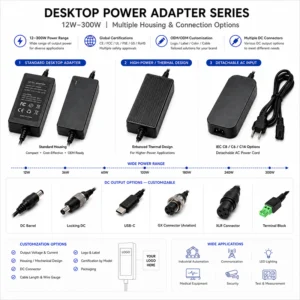
YHYadapter provides 24V and 48V AC/DC power solutions for industrial automation equipment and peripherals, including desktop power adapters and customized OEM/ODM configurations. Available options include different power levels, DC cables, connectors, output configurations, enclosure designs, and application-specific requirements.
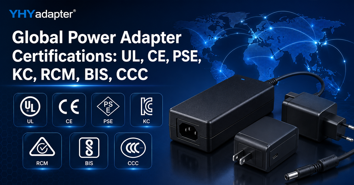
Safety, EMC, and market-access certifications—including UL, ETL, CE, FCC, and other regional approvals—are available depending on the model, configuration, and target market.
Need a 24V or 48V power solution for your industrial equipment?
Share your required voltage, continuous and peak current, connector, cable length, application, target market, and expected volume with our engineering team to evaluate the most suitable power platform and customization approach.
Related Resources
🔌 Related Products
🏭 Related Applications
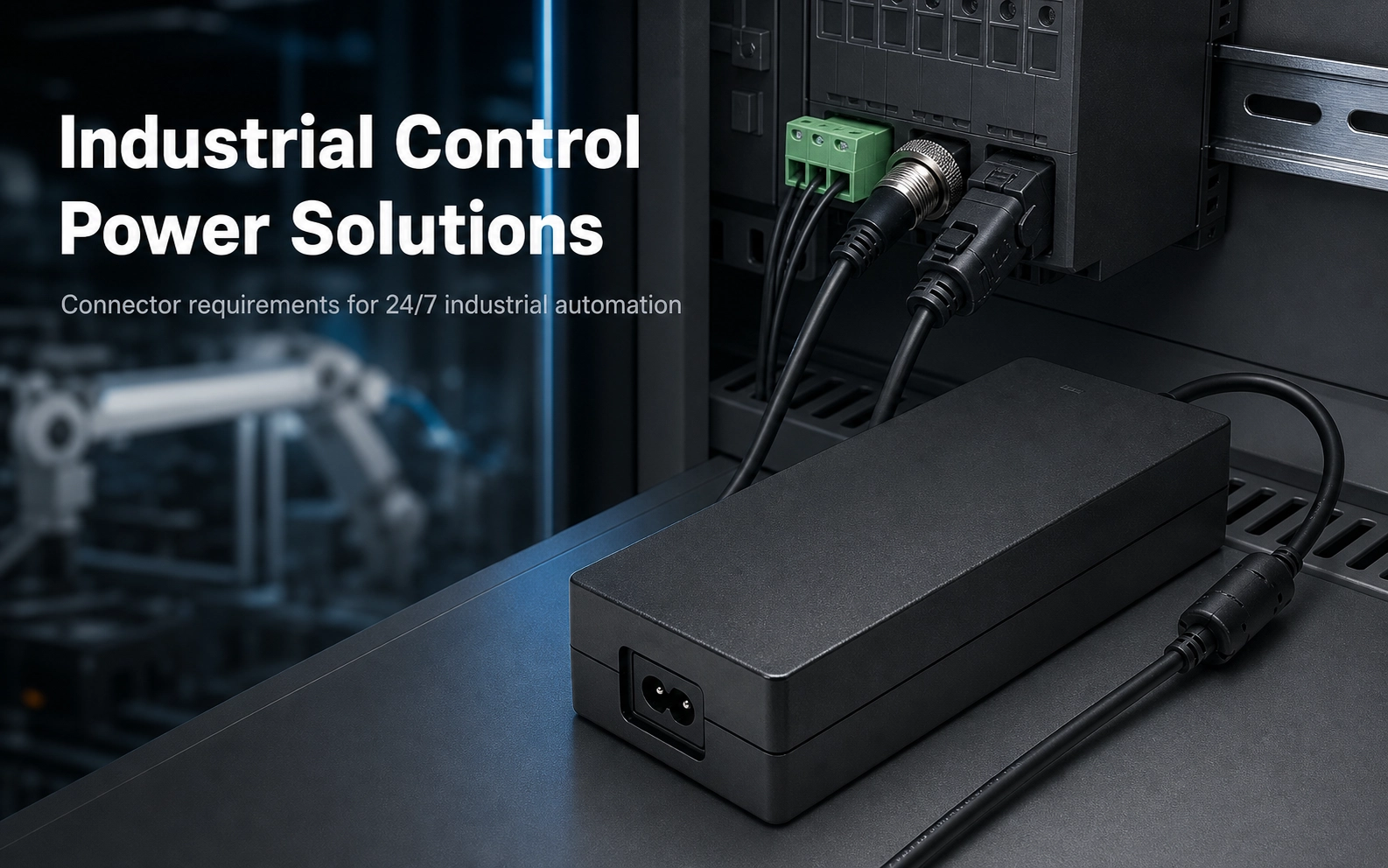
Industrial Control Power Solutions
Power solutions for PLC, CNC, servo and automation equipment
📖 Related Guides
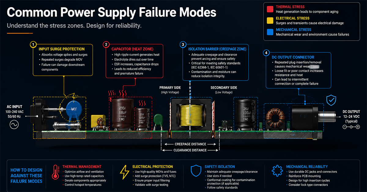
Common Power Supply Failure Modes
Common power supply failure modes and design countermeasures
✅ Related Certifications
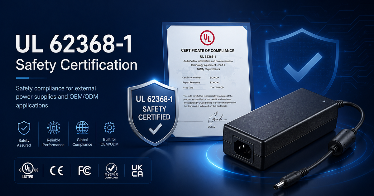
UL 62368-1 Safety Certification
Safety standard covering connector creepage/clearance, temperature rise, and strain relief requirements for IT/AV equipment power adapters.