
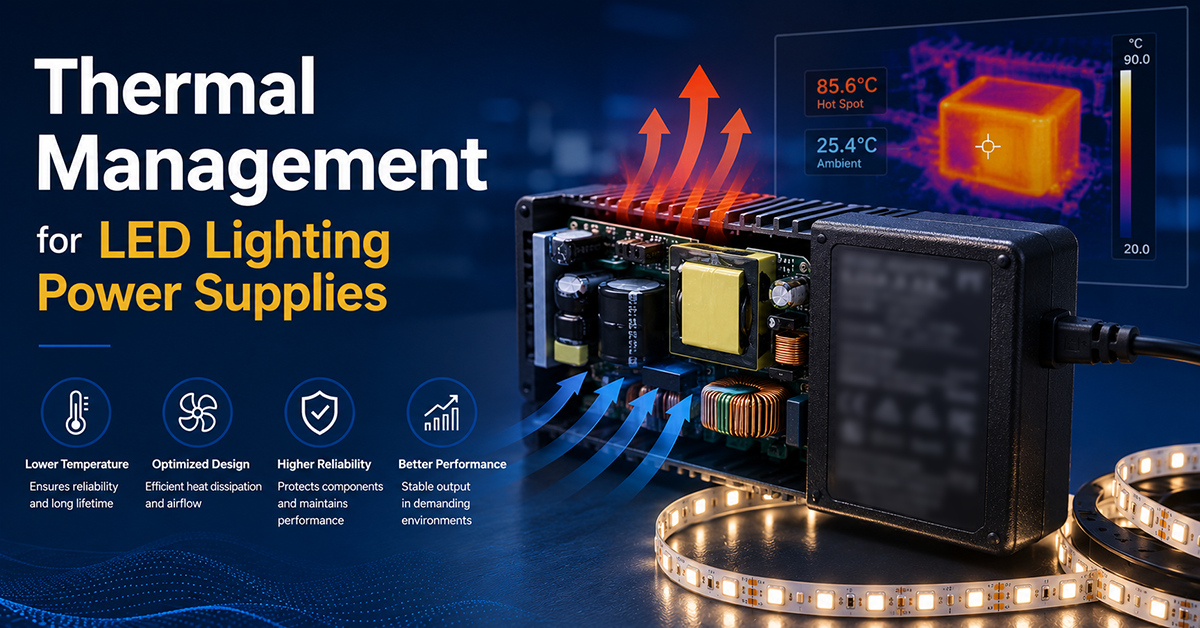
Thermal design decides how long an LED lighting power supply lasts and how much output it can actually deliver. The LEDs are a heat source, the enclosure retains heat, and the supply sits between them. Understanding where the heat goes — and which temperature the specification refers to — is what turns a derating curve into a design decision.
This guide covers the thermal considerations for power supplies used in LED lighting systems: what derating means, how case temperature differs from ambient and hotspot temperature, how capacitor lifetime follows temperature, how the luminaire enclosure behaves as a thermal system, and the strategies and measurements that keep the design inside its limits.
YHYadapter product positioning: The thermal guidance in this guide applies to constant-voltage (CV) AC/DC power adapters used in indoor LED lighting systems, and to the general principles that apply to LED power supplies. Constant-current drivers for luminaire-integrated designs are supplied by dedicated lighting driver manufacturers and are outside YHYadapter’s current product scope.
What Derating Means for an LED Supply
Every power supply reduces its rated output as ambient temperature rises. That behaviour — derating — is a protective measure that keeps internal component temperatures within their limits, and it is specific to the model.
A typical derating curve describes the maximum output as a function of ambient temperature. A supply might deliver its full rating up to a defined ambient, derate linearly above that, and reach a limit where further operation is not intended. Above the curve, the supply may reduce output, enter thermal protection, or shut down.
Two points follow for an OEM:
- The rating applies at the conditions in the curve. Selecting a supply by its headline wattage and installing it in a warmer enclosure changes the available output.
- The applicable derating curve is the one for the specific model. Derating behaviour differs by design, component selection and construction.
Case Temperature and Hotspot Temperature
A supply has several temperatures, and the specification refers to particular ones.
Ambient temperature is the air temperature around the supply. It is what the derating curve is usually defined against, and it is measured at a defined position — not simply taken to be the room temperature.
Case temperature (Tc) is the temperature at a defined point on the enclosure, chosen to represent the hottest accessible surface and to correlate with internal component temperatures. A maximum case temperature is the value the design must not exceed in operation, and exceeding it can reduce component life or trigger thermal protection.
Hotspot temperature is the temperature of the specific component or location that runs hottest internally — often a switching device, a magnetic component or a capacitor. It is not directly measurable from outside, and it is what internal thermal analysis estimates.
The distinction matters because the three can differ substantially. A supply in a closed luminaire may sit in an ambient well above the room, with a case temperature above that and a hotspot above either.
Capacitor Lifetime and Temperature
Electrolytic capacitors are commonly an important lifetime-limiting component in a power supply, and they are among the most temperature-sensitive.
Their degradation rate depends strongly on the capacitor’s core temperature, which is set by:
- The ambient inside the enclosure
- The ripple current flowing through the capacitor, which contributes internal heating
- The thermal path away from the capacitor body
The relationship is usually described as an Arrhenius-type rule, where a modest reduction in core temperature significantly extends service life. That is why a supply rated for a wide ambient expects its components — and the design’s thermal path — to be considered at that ambient, not at a bench temperature.
Lifetime statements in a datasheet usually assume reference conditions. Where the installation does not reproduce those conditions, the assumption is the part of the specification worth checking.
The Luminaire Enclosure as a Thermal System
In a luminaire, the enclosure is not just a housing; it is part of the thermal circuit.
- The LED array is a heat source, and its share of the input power leaves as heat rather than light.
- The supply adds its own losses, which rise as efficiency falls.
- The enclosure determines how that heat reaches the outside: through its surfaces by convection and radiation, and where the design intends it, by conduction to a thermally connected surface.
- The internal air distributes heat between the two sources, and its temperature is the ambient the supply actually sees.
At ceiling level, the room air itself is often warmer than at floor level, and a ceiling-mounted enclosure is still a closed volume. The internal ambient is therefore the quantity worth establishing, rather than the nominal room temperature.
Where the supply is mounted remotely from the LED array, in a separate compartment, its ambient can be substantially lower — which changes the derating position, at the cost of additional wiring and a separate enclosure.
Practical Thermal Strategies
The available strategies follow from where the heat has to go.
- Derate deliberately. Choose a supply whose derated output at the internal ambient covers the load, rather than relying on the headline rating.
- Separate the heat sources. Where the layout allows, keep the supply out of the hottest region near the LED array.
- Improve the path to the outside. A thermally connected path from the supply to a cooler external surface is more effective than internal air movement alone.
- Consider the thermal interface. Where the supply is mounted against a surface, the interface material and the contact area affect how much heat is conducted.
- Reduce the losses. A more efficient supply produces less heat in the first place, which eases every other measure.
None of these is free; each adds cost, space or complexity. The point is to make the thermal case explicit so the trade is a decision rather than an oversight.
Verifying the Thermal Case
Thermal design is confirmed by measurement, not by assumption.
- Measure the ambient at the position the supply occupies, inside the enclosure, under representative load
- Measure the case at the specified point and compare it with the limit for the model
- Record the load and the duration, since steady state is what the components experience
- Repeat at the worst realistic conditions — maximum load, maximum expected ambient, and any condition that adds heat
The measurements are then compared with the model’s derating and temperature limits. Where a measurement is close to a limit, the margin is a design question rather than a testing one.
Frequently Asked Questions
What does a derating curve actually tell me?
The maximum output the supply can deliver at a given ambient temperature. Above the stated conditions the available output falls, so the curve — not the headline rating — is what applies in an installation.
What is the difference between ambient, case and hotspot temperature?
Ambient is the air around the supply; case temperature is measured at a defined point on the enclosure; hotspot temperature is the hottest internal location. They can differ substantially, and the specification refers to specific ones.
Why does capacitor temperature matter so much?
Electrolytic capacitors are commonly lifetime-limiting, and their degradation rate rises with core temperature. A modest reduction in that temperature can extend service life significantly.
Does the luminaire enclosure change the supply requirement?
Yes. The enclosure is part of the thermal circuit: the LEDs add heat, and the enclosure decides how it leaves. The internal ambient, rather than the room temperature, is the quantity the derating position should be checked against.
How should the thermal case be verified?
By measuring the ambient at the supply’s position and the case at its specified point, under representative load and at the worst realistic conditions, then comparing the results with the model’s limits.
Related Resources
- LED Lighting
- LED Lighting Power Supply Selection Guide
- Indoor LED Power Supply Design (link after publication)